
顶点数据的乘积导致轮廓不均匀(着色实验室unity3d)
我在Unity3D的着色器实验室中创建了一个简单的轮廓着色器,它有两次传递:一次通过沿顶点法线乘以顶点信息来缩放对象,然后传递两次绘制对象的常规(基本通过)版本。问题在大纲通行证的代码中:
Pass {
    Name "OUTLINE"

    ZWrite Off
    Blend SrcAlpha OneMinusSrcAlpha // Normal

    CGPROGRAM
    #pragma vertex vert
    #pragma fragment frag
    #include "UnityCG.cginc"

    struct appdata {
        float4 vertex : POSITION;
        float3 normal : NORMAL;
    };

    struct v2f {
        float4 position : POSITION;
        float3 normal : NORMAL;
    };

    uniform float _OutlineWidth;
    uniform float4 _OutlineColor;

    v2f vert(appdata v) {
        v.vertex.xyz *=  _OutlineWidth;

        v2f o;
        o.position = UnityObjectToClipPos(v.vertex);
        return o;
    }

    half4 frag(v2f i) : COLOR {
        return _OutlineColor;
    }

    ENDCG
}_OutlineWidth和_OutlineColor分别属于范围型和颜色型。我已经将这个着色器应用于几个以编程方式创建的“tetromino样”网格。结果是(点击链接):
正如您所看到的,创建了一个大纲,但是轮廓沿对象的外部边缘并不是均匀的宽度。沿着其中一张脸,轮廓更大--它沿着离形状中心最远的脸更大。对于非凸形状,问题被放大;轮廓甚至可能根本不包括形状:
我知道,这是由于顶点位置相对于形状的中心,而直线v.vertex.xyz *= _OutlineWidth只是将这个位置乘以一个恒定的量(使它离物体的中心更远)。如何修改代码,以便计算轮廓像素,使其独立于形状的中心,并与对象的真实轮廓完整?
回答 1
Stack Overflow用户
发布于 2018-12-20 21:06:37
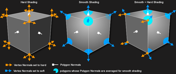
正如@Gnietschow所说,您需要使用这些顶点的“光滑法线”来知道扩展轮廓的方向:
来源: FrostSoft
一种方法是计算C#中的软法线,然后将它们赋值为顶点数据。此示例使用uv2和uv3通道来保存平滑的正常组件:
Mesh mesh = GetComponent<MeshFilter>().mesh;

Vector3[] meshVertices = mesh.vertices;
//map vertex positions to the ids of all vertices at that position
Dictionary<Vector3, List<int>> vertexMerge = new Dictionary<Vector3, List<int>>();
for(int i = 0; i < mesh.vertexCount; i++) {
    Vector3 vectorPosition = meshVertices[i];

    if(!vertexMerge.ContainsKey(vectorPosition)) {
        //if not already in our collection as a key, add it as a key
        vertexMerge.Add(vectorPosition, new List<int>());
    }

    //add the vertex id to our collection
    vertexMerge[vectorPosition].Add(i);
}

//map vertexIDs to the averaged normal
Vector3[] meshNormals = mesh.normals;
Vector3[] vertexAveragedNormals = new Vector3[mesh.vertexCount];

foreach (List<int> duplicatedVertices in vertexMerge.Values) {
    //calculate average normal
    Vector3 sumOfNormals = Vector3.zero;
    foreach (int vertexIndex in duplicatedVertices) {
        sumOfNormals += meshNormals[vertexIndex];
    }

    Vector3 averagedNormal = (sumOfNormals /= duplicatedVertices.Count).normalized; //average is sum divided by the number of summed elements

    //write the result to our output
    foreach (int vertexIndex in duplicatedVertices) {
        vertexAveragedNormals[vertexIndex] = averagedNormal;
    }
}


//write the result to mesh.
//x and y components shoved into uv3, z component shoved into uv4, with w component of 1.
Vector2[] vertexAveragedNormalsXY = new Vector2[mesh.vertexCount];
Vector2[] vertexAveragedNormalsZW = new Vector2[mesh.vertexCount];
for(int i = 0; i < mesh.vertexCount; i++) {
    Vector3 normal = vertexAveragedNormals[i];
    vertexAveragedNormalsXY[i] = new Vector2(normal.x, normal.y);
    vertexAveragedNormalsZW[i] = new Vector2(normal.z, 1);
}

mesh.uv3 = vertexAveragedNormalsXY;
mesh.uv4 = vertexAveragedNormalsZW;来源:红鳍鱼-
然后,使用TEXCOORD2和TEXCOORD3重建vert中的平滑法线。使用这些可以相应地移动顶点位置,同时保持顶点正常与任何照明用途相同的硬法线:
Pass {
    Name "OUTLINE"

    ZWrite Off
    Blend SrcAlpha OneMinusSrcAlpha // Normal

    CGPROGRAM
    #pragma vertex vert
    #pragma fragment frag
    #include "UnityCG.cginc"

    struct appdata {
        float4 vertex : POSITION;
        float3 normal : NORMAL;
        float4 texcoord2 : TEXCOORD2;
        float4 texcoord3 : TEXCOORD3;
    };

    struct v2f {
        float4 position : POSITION;
        float3 normal : NORMAL;
    };

    uniform float _OutlineWidth;
    uniform float4 _OutlineColor;

    v2f vert(appdata v) {
        // add the outline width in the direction of the shared normal
        float3 sharedNormal = float3(v.texcoord2.xy, v.texcoord3.x);

        v.vertex.xyz +=  _OutlineWidth * sharedNormal;

        v2f o;
        o.position = UnityObjectToClipPos(v.vertex);
        return o;
    }

    half4 frag(v2f i) : COLOR {
        return _OutlineColor;
    }

    ENDCG
}https://stackoverflow.com/questions/53799822
复制相似问题
腾讯云开发者

Copyright © 2013 - 2026 Tencent Cloud. All Rights Reserved. 腾讯云 版权所有
深圳市腾讯计算机系统有限公司 ICP备案/许可证号:粤B2-20090059 ![]() 粤公网安备44030502008569号
粤公网安备44030502008569号
腾讯云计算(北京)有限责任公司 京ICP证150476号 | 京ICP备11018762号