
轮廓-轮廓着色
我正在尝试实现GLSL着色器,这将突出渲染3D网格的外部边缘。问题是我无法访问OpenGL客户端代码,所以只能在GLSL着色器中进行。
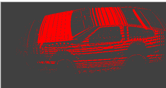
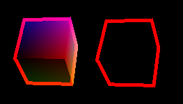
我的第一次尝试是使用/采用这着色器来自Unity,并在OpenGL GLSL中使用。在这里,它应该是什么样子:
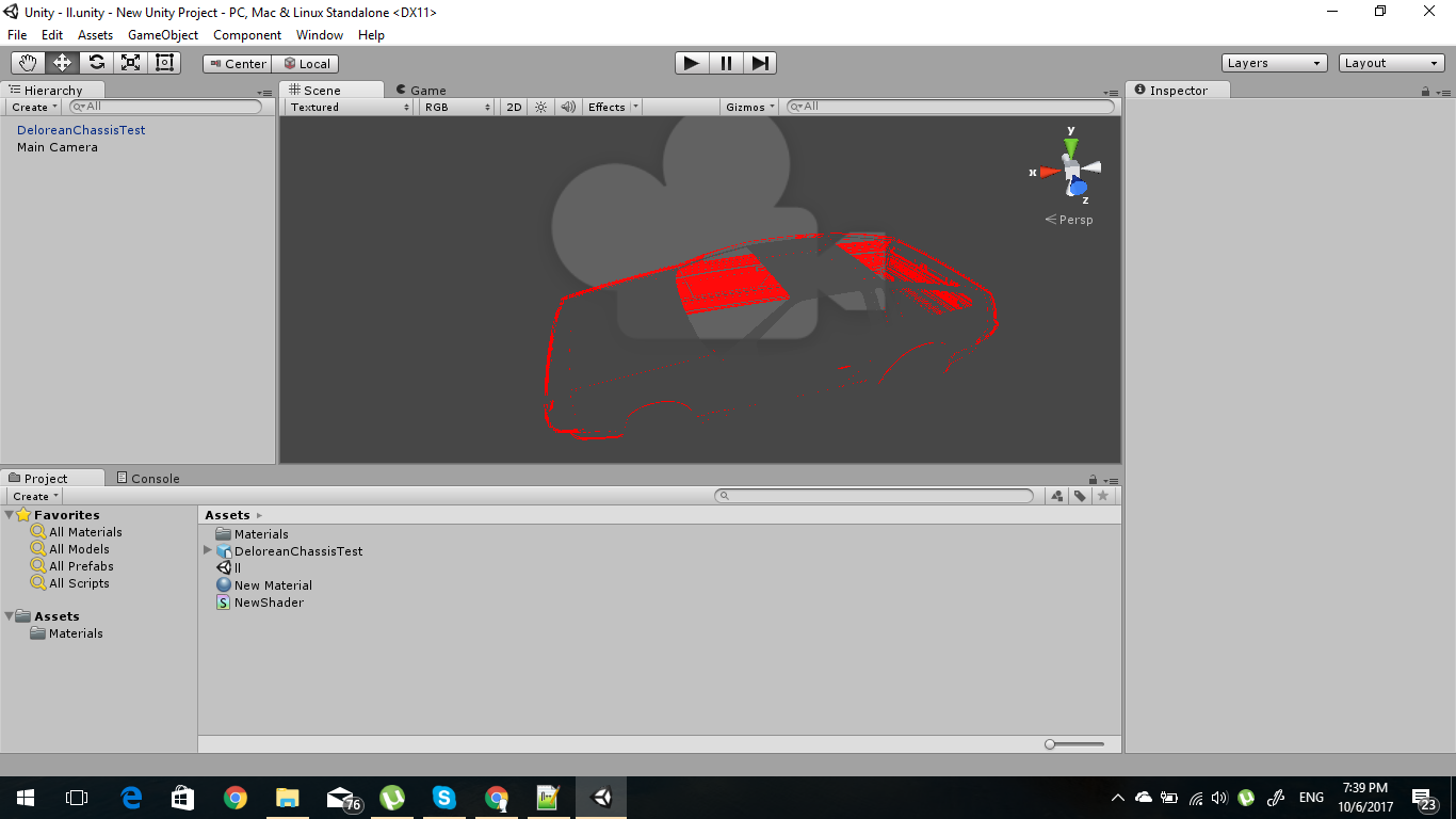
我得到的是:
我不确定我是否正确地计算了这些东西,但是正如你所看到的,输出远没有达到我的预期。
这是食人魔的材料
material Chassis
    {
    technique
        {
        pass standard
            {
            cull_software back
            scene_blend zero one
            }
        pass psssm
            {
            cull_software front
            scene_blend src_alpha one_minus_src_alpha
            vertex_program_ref reflection_cube_specularmap_normalmap_vs100
                {
                param_named_auto modelViewProjectionMatrix worldviewproj_matrix
                param_named_auto normalMatrix inverse_transpose_world_matrix
                param_named_auto modelView worldview_matrix
                param_named_auto camera_world_position camera_position
                param_named_auto inverse_projection_matrix inverse_projection_matrix
                param_named_auto  projection_matrix projection_matrix
                param_named_auto  p_InverseModelView inverse_worldview_matrix
                }
            fragment_program_ref reflection_cube_specularmap_normalmap_fs100
                {
                }
            }
        }
    }
这里是顶点着色器
#version 140
#define lowp
#define mediump
#define highp

in vec4 vertex;
in vec3 normal;

uniform mat4 normalMatrix;
uniform mat4 modelViewProjectionMatrix;
uniform mat4 modelView;
uniform vec3 camera_world_position;
uniform mat4 projection_matrix;
uniform mat4 inverse_projection_matrix;
void main()
   {
   vec4 pos = modelViewProjectionMatrix * vertex;
   mat4 modelView = inverse_projection_matrix * modelViewProjectionMatrix;

   vec4 norm   =   inverse(transpose(modelView)) * vec4(normal, 0.0);
   vec2 offset =   vec2( norm.x * projection_matrix[0][0], norm.y * projection_matrix[1][1] );

   pos.xy += offset * pos.z * 0.18;
   gl_Position = pos;
} 编辑:我添加了食人魔使用的素材脚本,并添加了顶点着色代码。
回答 1
Stack Overflow用户
发布于 2017-10-07 08:45:58
我假设单个复杂的三维网格。我会用2次pass渲染来完成这个任务:
- 透明屏幕
让
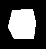
(0,0,0)作为清晰的颜色。 - 渲染网格
禁用深度输出,测试(或随后清除)。不要仅仅使用一些预定义的颜色来填充阴影,例如,
(1,1,1)让简单的立方体这样做:
- 读取帧缓冲区并将其用作纹理
因此,要么使用FBO并为#1、#2呈现纹理,要么使用
glReadPixels作为纹理加载回GPU (我知道速度较慢,但也适用于英特尔)。有关更多信息,请参见此处的两个答案:
- [OpenGL Scale Single Pixel Line](https://stackoverflow.com/a/43654398/2521214)
- 带背景色的透明屏幕
- 渲染
所以要么渲染
GL_QUAD覆盖整个屏幕,要么渲染你的网格与阴影和任何你想要的。您还需要将纹理从前面的步骤传递到GLSL中。 在片段中,像往常一样呈现..。但最后还加上了以下内容: 扫描所有纹理周围的当前片段屏幕位置,直到距离,等于轮廓厚度的纹理,从上一步。如果在其中发现任何黑色像素,则用大纲颜色覆盖输出的颜色。你甚至可以调整它与黑色的最小距离。 这与此非常相似:
- [How to implement 2D raycasting light effect in GLSL](https://stackoverflow.com/a/34708022/2521214)但要简单得多。结果如下:
我以我的虚拟现实中的着色器分析为例,并将其转换为:
片段:
// Fragment
#version 400 core
#extension GL_ARB_explicit_uniform_location : enable
layout(location =64) uniform vec3 lt_pnt_pos;// point light source position [GCS]
layout(location =67) uniform vec3 lt_pnt_col;// point light source color&strength
layout(location =70) uniform vec3 lt_amb_col;// ambient light source color&strength
in vec3 LCS_pos;        // fragment position [LCS]
in vec3 pixel_pos;      // fragment position [GCS]
in vec3 pixel_col;      // fragment surface color
in vec3 pixel_nor;      // fragment surface normal [GCS]
out vec4 col;

// outline
uniform sampler2D txr;  // texture from previous pass
uniform int thickness;  // [pixels] outline thickness
uniform float xs,ys;    // [pixels] texture/screen resolution
void main()
    {
    // standard rendering
    float li;
    vec3 c,lt_dir;
    lt_dir=normalize(lt_pnt_pos-pixel_pos); // vector from fragment to point light source in [GCS]
    li=dot(pixel_nor,lt_dir);
    if (li<0.0) li=0.0;
    c=pixel_col*(lt_amb_col+(lt_pnt_col*li));

    // outline effect
    if (thickness>0)            // thickness effect in second pass
        {
        int i,j,r=thickness;
        float xx,yy,rr,x,y,dx,dy;
        dx=1.0/xs;              // texel size
        dy=1.0/ys;
        x=gl_FragCoord.x*dx;
        y=gl_FragCoord.y*dy;
        rr=thickness*thickness;
        for (yy=y-(float(thickness)*dy),i=-r;i<=r;i++,yy+=dy)
         for (xx=x-(float(thickness)*dx),j=-r;j<=r;j++,xx+=dx)
          if ((i*i)+(j*j)<=rr)
           if ((texture(txr,vec2(xx,yy)).r)<0.01)
            {
            c=vec3(1.0,0.0,0.0);    // outline color
            i=r+r+1;
            j=r+r+1;
            break;
            }
        }
    else c=vec3(1.0,1.0,1.0);   // render with white in first pass

    // output color
    col=vec4(c,1.0);
}顶点着色器没有任何更改:
// Vertex
#version 400 core
#extension GL_ARB_explicit_uniform_location : enable
layout(location = 0) in vec3 pos;
layout(location = 2) in vec3 nor;
layout(location = 3) in vec3 col;
layout(location = 0) uniform mat4 m_model;  // model matrix
layout(location =16) uniform mat4 m_normal; // model matrix with origin=(0,0,0)
layout(location =32) uniform mat4 m_view;   // inverse of camera matrix
layout(location =48) uniform mat4 m_proj;   // projection matrix
out vec3 LCS_pos;       // fragment position [LCS]
out vec3 pixel_pos;     // fragment position [GCS]
out vec3 pixel_col;     // fragment surface color
out vec3 pixel_nor;     // fragment surface normal [GCS]

void main()
    {
    LCS_pos=pos;
    pixel_col=col;
    pixel_pos=(m_model*vec4(pos,1)).xyz;
    pixel_nor=(m_normal*vec4(nor,1)).xyz;
    gl_Position=m_proj*m_view*m_model*vec4(pos,1);
}CPU侧代码如下所示:
//---------------------------------------------------------------------------
#include <vcl.h>
#pragma hdrstop
#include "Unit1.h"
#include "gl_simple.h"
//---------------------------------------------------------------------------
#pragma package(smart_init)
#pragma resource "*.dfm"
TForm1 *Form1;
//---------------------------------------------------------------------------
GLfloat lt_pnt_pos[3]={+2.5,+2.5,+2.5};
GLfloat lt_pnt_col[3]={0.8,0.8,0.8};
GLfloat lt_amb_col[3]={0.2,0.2,0.2};
GLuint txrid=0;
GLfloat animt=0.0;
//---------------------------------------------------------------------------
// https://stackoverflow.com/q/46603878/2521214
//---------------------------------------------------------------------------
void gl_draw()
    {
    // load values into shader
    GLint i,id;
    GLfloat m[16];
    glUseProgram(prog_id);

    GLfloat x,y,z,d=0.25;

    id=glGetUniformLocation(prog_id,"txr"); glUniform1i(id,0);
    id=glGetUniformLocation(prog_id,"xs"); glUniform1f(id,xs);
    id=glGetUniformLocation(prog_id,"ys"); glUniform1f(id,ys);

    id=64; glUniform3fv(id,1,lt_pnt_pos);
    id=67; glUniform3fv(id,1,lt_pnt_col);
    id=70; glUniform3fv(id,1,lt_amb_col);
    glGetFloatv(GL_MODELVIEW_MATRIX,m);
    id=0; glUniformMatrix4fv(id,1,GL_FALSE,m);
    m[12]=0.0; m[13]=0.0; m[14]=0.0;
    id=16; glUniformMatrix4fv(id,1,GL_FALSE,m);
    for (i=0;i<16;i++) m[i]=0.0; m[0]=1.0; m[5]=1.0; m[10]=1.0; m[15]=1.0;
    id=32; glUniformMatrix4fv(id,1,GL_FALSE,m);
    glGetFloatv(GL_PROJECTION_MATRIX,m);
    id=48; glUniformMatrix4fv(id,1,GL_FALSE,m);


    // draw VAO cube (no outline)
    id=glGetUniformLocation(prog_id,"thickness"); glUniform1i(id,0);
    glClear(GL_COLOR_BUFFER_BIT | GL_DEPTH_BUFFER_BIT);
    vao_draw(); // render cube

    // copy frame buffer to CPU memory and than back to GPU as Texture
    BYTE *map=new BYTE[xs*ys*4];
    glReadPixels(0,0,xs,ys,GL_RGB,GL_UNSIGNED_BYTE,map);    // framebuffer -> map[]
    glEnable(GL_TEXTURE_2D);
    glBindTexture(GL_TEXTURE_2D,txrid);
    glTexImage2D(GL_TEXTURE_2D, 0, GL_RGB, xs, ys, 0, GL_RGB, GL_UNSIGNED_BYTE, map); // map[] -> texture txrid
    delete[] map;

    // draw VAO cube (outline)
    id=glGetUniformLocation(prog_id,"thickness"); glUniform1i(id,5);
    glClear(GL_COLOR_BUFFER_BIT | GL_DEPTH_BUFFER_BIT);
    vao_draw(); // render cube
    glDisable(GL_TEXTURE_2D);

    // turn of shader
    glUseProgram(0);

    // rotate the cube to see animation
    glMatrixMode(GL_MODELVIEW);
//  glRotatef(1.0,0.0,1.0,0.0);
//  glRotatef(1.0,1.0,0.0,0.0);

    glFlush();
    SwapBuffers(hdc);
    }
//---------------------------------------------------------------------------
__fastcall TForm1::TForm1(TComponent* Owner):TForm(Owner)
    {
    gl_init(Handle);

    glGenTextures(1,&txrid);
    glEnable(GL_TEXTURE_2D);
    glBindTexture(GL_TEXTURE_2D,txrid);
    glPixelStorei(GL_UNPACK_ALIGNMENT, 4);
    glTexParameteri(GL_TEXTURE_2D, GL_TEXTURE_WRAP_S,GL_CLAMP_TO_EDGE);
    glTexParameteri(GL_TEXTURE_2D, GL_TEXTURE_WRAP_T,GL_CLAMP_TO_EDGE);
    glTexParameteri(GL_TEXTURE_2D, GL_TEXTURE_MAG_FILTER,GL_NEAREST);
    glTexParameteri(GL_TEXTURE_2D, GL_TEXTURE_MIN_FILTER,GL_NEAREST);
    glTexEnvf(GL_TEXTURE_ENV, GL_TEXTURE_ENV_MODE,GL_COPY);
    glDisable(GL_TEXTURE_2D);


    int hnd,siz; char vertex[4096],fragment[4096];
    hnd=FileOpen("normal_shading.glsl_vert",fmOpenRead); siz=FileSeek(hnd,0,2); FileSeek(hnd,0,0); FileRead(hnd,vertex  ,siz); vertex  [siz]=0; FileClose(hnd);
    hnd=FileOpen("normal_shading.glsl_frag",fmOpenRead); siz=FileSeek(hnd,0,2); FileSeek(hnd,0,0); FileRead(hnd,fragment,siz); fragment[siz]=0; FileClose(hnd);
    glsl_init(vertex,fragment);
//  hnd=FileCreate("GLSL.txt"); FileWrite(hnd,glsl_log,glsl_logs); FileClose(hnd);

    int i0,i;
    mm_log->Lines->Clear();
    for (i=i0=0;i<glsl_logs;i++)
     if ((glsl_log[i]==13)||(glsl_log[i]==10))
        {
        glsl_log[i]=0;
        mm_log->Lines->Add(glsl_log+i0);
        glsl_log[i]=13;
        for (;((glsl_log[i]==13)||(glsl_log[i]==10))&&(i<glsl_logs);i++);
        i0=i;
        }
    if (i0<glsl_logs) mm_log->Lines->Add(glsl_log+i0);

    vao_init();
    }
//---------------------------------------------------------------------------
void __fastcall TForm1::FormDestroy(TObject *Sender)
    {
    glDeleteTextures(1,&txrid);
    gl_exit();
    glsl_exit();
    vao_exit();
    }
//---------------------------------------------------------------------------
void __fastcall TForm1::FormResize(TObject *Sender)
    {
    gl_resize(ClientWidth,ClientHeight-mm_log->Height);
    glMatrixMode(GL_PROJECTION);
    glTranslatef(0,0,-15.0);

    glMatrixMode(GL_MODELVIEW);
    glRotatef(-15.0,0.0,1.0,0.0);
    glRotatef(-125.0,1.0,0.0,0.0);
    }
//---------------------------------------------------------------------------
void __fastcall TForm1::FormPaint(TObject *Sender)
    {
    gl_draw();
    }
//---------------------------------------------------------------------------
void __fastcall TForm1::Timer1Timer(TObject *Sender)
    {
    gl_draw();
    animt+=0.02; if (animt>1.5) animt=-0.5;
    Caption=animt;
    }
//---------------------------------------------------------------------------
void __fastcall TForm1::FormMouseWheel(TObject *Sender, TShiftState Shift, int WheelDelta, TPoint &MousePos, bool &Handled)
    {
    GLfloat dz=2.0;
    if (WheelDelta<0) dz=-dz;
    glMatrixMode(GL_PROJECTION);
    glTranslatef(0,0,dz);
    gl_draw();
    }
//---------------------------------------------------------------------------
与往常一样,代码正在使用/基于以下内容:
Notes
如果您有多个对象,那么在#2中为每个对象使用不同的颜色。然后在#5中,扫描任何不同的颜色,然后是在当前位置的纹理,而不是扫描黑色。
这也可以在2D图像上完成,而不是使用网格。你只需要知道背景颜色。因此,您也可以使用预渲染/抓取/截图图像。
您可以添加discard,或者更改最终的if逻辑来改变行为(就像您只想要轮廓,内部没有网格等等)。或者你可以添加轮廓颜色渲染颜色,而不是直接分配它来获得高亮的印象.而不是着色
(见a)、b)、c)修改后的片段中的选项:
// Fragment
#version 400 core
#extension GL_ARB_explicit_uniform_location : enable
layout(location =64) uniform vec3 lt_pnt_pos;// point light source position [GCS]
layout(location =67) uniform vec3 lt_pnt_col;// point light source color&strength
layout(location =70) uniform vec3 lt_amb_col;// ambient light source color&strength
in vec3 LCS_pos;        // fragment position [LCS]
in vec3 pixel_pos;      // fragment position [GCS]
in vec3 pixel_col;      // fragment surface color
in vec3 pixel_nor;      // fragment surface normal [GCS]
out vec4 col;

// outline
uniform sampler2D txr;  // texture from previous pass
uniform int thickness;  // [pixels] outline thickness
uniform float xs,ys;    // [pixels] texture/screen resolution
void main()
    {
    // standard rendering
    float li;
    vec3 c,lt_dir;
    lt_dir=normalize(lt_pnt_pos-pixel_pos); // vector from fragment to point light source in [GCS]
    li=dot(pixel_nor,lt_dir);
    if (li<0.0) li=0.0;
    c=pixel_col*(lt_amb_col+(lt_pnt_col*li));

    // outline effect
    if (thickness>0)            // thickness effect in second pass
        {
        int i,j,r=thickness;
        float xx,yy,rr,x,y,dx,dy;
        dx=1.0/xs;              // texel size
        dy=1.0/ys;
        x=gl_FragCoord.x*dx;
        y=gl_FragCoord.y*dy;
        rr=thickness*thickness;
        for (yy=y-(float(thickness)*dy),i=-r;i<=r;i++,yy+=dy)
         for (xx=x-(float(thickness)*dx),j=-r;j<=r;j++,xx+=dx)
          if ((i*i)+(j*j)<=rr)
           if ((texture(txr,vec2(xx,yy)).r)<0.01)
            {
            c =vec3(1.0,0.0,0.0);   // a) assign outline color
//          c+=vec3(1.0,0.0,0.0);   // b) add outline color
            i=r+r+1;
            j=r+r+1;
            r=0;
            break;
            }
//      if (r!=0) discard; // c) do not render inside
        }
    else c=vec3(1.0,1.0,1.0);   // render with white in first pass

    // output color
    col=vec4(c,1.0);
}光滑边的Edit1单程方法
由于您无法访问客户端代码,此方法将只在着色器中工作。对于光滑(弯曲)边缘形状,表面法线接近垂直于相机的视轴(z)。所以它们之间的dot接近于零。这可以直接利用..。在此更新着色器:
顶点
// Vertex
#version 400 core
#extension GL_ARB_explicit_uniform_location : enable
layout(location = 0) in vec3 pos;
layout(location = 2) in vec3 nor;
layout(location = 3) in vec3 col;
layout(location = 0) uniform mat4 m_model;  // model matrix
layout(location =16) uniform mat4 m_normal; // model matrix with origin=(0,0,0)
layout(location =32) uniform mat4 m_view;   // inverse of camera matrix
layout(location =48) uniform mat4 m_proj;   // projection matrix
out vec3 pixel_pos;     // fragment position [GCS]
out vec3 pixel_col;     // fragment surface color
out vec3 pixel_nor;     // fragment surface normal [GCS]
out vec3 view_nor;     // surface normal in camera [LCS]

void main()
    {
    pixel_col=col;
    pixel_pos=(m_model*vec4(pos,1)).xyz;
    pixel_nor=(m_normal*vec4(nor,1)).xyz;

    mat4 m;
    m=m_model*m_view;                   // model view matrix
    m[3].xyz=vec3(0.0,0.0,0.0);         // with origin set to (0,0,0)
    view_nor=(m*vec4(nor,1.0)).xyz;     // object local normal to camera local normal

    gl_Position=m_proj*m_view*m_model*vec4(pos,1);
    }
片段
// Fragment
#version 400 core
#extension GL_ARB_explicit_uniform_location : enable
layout(location =64) uniform vec3 lt_pnt_pos;// point light source position [GCS]
layout(location =67) uniform vec3 lt_pnt_col;// point light source color&strength
layout(location =70) uniform vec3 lt_amb_col;// ambient light source color&strength
in vec3 pixel_pos; // fragment position [GCS]
in vec3 pixel_col; // fragment surface color
in vec3 pixel_nor; // fragment surface normal [GCS]
out vec4 col;
// outline
in vec3 view_nor; // surface normal in camera [LCS]
void main()
{
// standard rendering
float li;
vec3 c,lt_dir;
lt_dir=normalize(lt_pnt_pos-pixel_pos); // vector from fragment to point light source in [GCS]
li=dot(pixel_nor,lt_dir);
if (li<0.0) li=0.0;
c=pixel_col*(lt_amb_col+(lt_pnt_col*li));
// outline effect
if (abs(dot(view_nor,vec3(0.0,0.0,1.0)))<=0.5) c=vec3(1.0,0.0,0.0);
// output color
col=vec4(c,1.0);
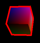
}在这里预览:

正如你所看到的,它适用于光滑的物体,但是对于像立方体这样锋利的边缘,这根本不起作用.您可以使用与以前方法相同的组合(a,b,c)。
m保存初始设置为(0,0,0)的模型视图矩阵。这使得它能够进行向量转换(不进行翻译)。有关更多信息,请参见对4x4齐次变换矩阵的理解。
0.5在网点乘积结果中的if是轮廓的厚度。0.0表示没有大纲,1.0表示整个对象是大纲。
https://stackoverflow.com/questions/46603878
复制相似问题
腾讯云开发者

Copyright © 2013 - 2026 Tencent Cloud. All Rights Reserved. 腾讯云 版权所有
深圳市腾讯计算机系统有限公司 ICP备案/许可证号:粤B2-20090059 ![]() 粤公网安备44030502008569号
粤公网安备44030502008569号
腾讯云计算(北京)有限责任公司 京ICP证150476号 | 京ICP备11018762号