
我的VHDL波形图错了
我目前正在用DesignWorks 5编写一些VHDL代码来制作CPU。我的电路波形图并没有输出它应该输出的内容。我所有的代码都编译得很好。有办法解决这个问题吗?我觉得我错过了一些又小又蠢的东西。提前谢谢你的帮助。(我没有足够的声誉来发布2个链接!)
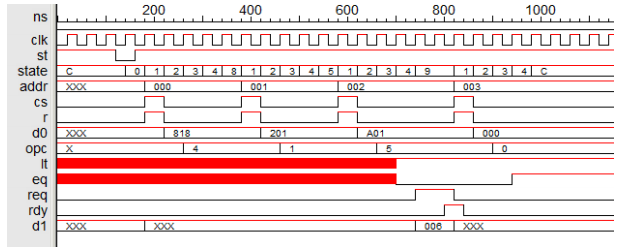
电路的波形应该是这样的:imger.com/IBtoFuO
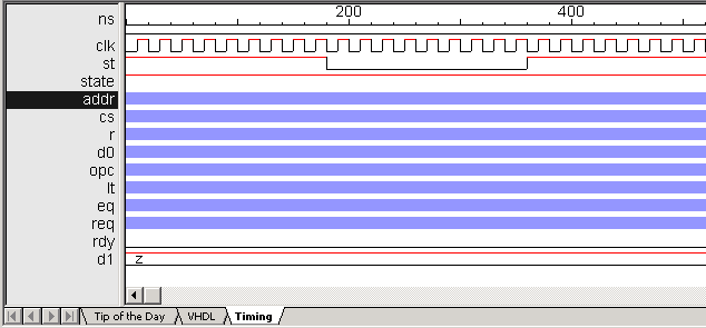
下面是我的波形所显示的:imger.com/rcRTrLR
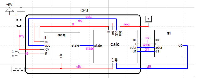
下面是CPU的样子:imger.com/Ek1G3rZ
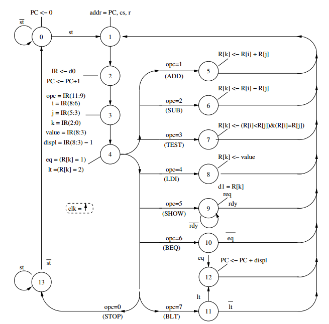
下面是状态机图的样子:imger.com/AeCaPof
我在三个实体中的每一个单独的文件中都有代码。SEQ是我的状态转换,CALC是我断言的输出转换,M是我提供的内存。
以下是我的状态转换代码:
library IEEE;
use IEEE.std_logic_arith.all;
use IEEE.std_logic_1164.all;

--Finish Entity Definition
entity SEQ is
    port(clk, st, lt, eq : in std_logic;
         opc : in std_logic_vector(11 downto 9);
         rdy : in std_logic;
         new_state : out std_logic_vector(3 downto 0));  --entity transfers over
end SEQ;

architecture behav of SEQ is
begin
--state transition process
    process is
    variable curr_state : std_logic_vector(3 downto 0) := "1101";
    begin
    if clk = '1' then
    case curr_state is
        when "0000" => curr_state := "0001";
        when "0001" => curr_state := "0010";
        when "0010" => curr_state := "0011";
        when "0011" => curr_state := "0100";
        when "0100" =>
            if    opc = "000" then curr_state := "1101";
            elsif opc = "001" then curr_state := "0101";
            elsif opc = "010" then curr_state := "0110";
            elsif opc = "011" then curr_state := "0111";
            elsif opc = "100" then curr_state := "1000";
            elsif opc = "101" then curr_state := "1001";
            elsif opc = "110" then curr_state := "1010";
            elsif opc = "111" then curr_state := "1011";
            end if;
        when "0101" => curr_state := "0001";
        when "0110" => curr_state := "0001";
        when "0111" => curr_state := "0001";
        when "1000" => curr_state := "0001";
        when "1001" =>
            if rdy = '1' then curr_state := "0001";
            elsif rdy = '0' then curr_state := "1001";
            end if;
        when "1010" =>
            if eq = '1' then curr_state := "1100";
            elsif eq = '0' then curr_state := "0001";
            end if;
        when "1011" =>
            if lt = '1' then curr_state := "1100";
            elsif lt = '0' then curr_state := "0001";
            end if;
        when "1100" => curr_state := "0001";
        when "1101" =>
            if st = '1' then curr_state := "1101";
            elsif st = '0' then curr_state := "0000";
            end if;
    end case;
    wait on clk;
    new_state <= curr_state;
    end if;
    end process;
end behav;
以下是我断言的输出代码:
library IEEE;
use IEEE.std_logic_arith.all;
use IEEE.std_logic_1164.all;

--Entity Definition
entity CALC is
    port( clk, cs, r, req, lt, eq : in std_logic;
          new_state : in std_logic_vector(3 downto 0);
          opc : in std_logic_vector(11 downto 9);
          addr : in std_logic_vector(8 downto 0); -- 2^9
          d0 : in std_logic_vector(11 downto 0);
          d1 : out std_logic_vector(11 downto 0)); --ignore stuff on arrows
end CALC;

architecture behav of CALC is
type memory is array(0 to 7) of std_logic_vector(11 downto 0);
begin
--Asserted output process
    process is
    variable curr_state : std_logic_vector(3 downto 0) := "1101";
    variable cs_val, r_val, req_val, lt_val, eq_val: std_logic;
    variable opc_val:std_logic_vector(11 downto 9);
    variable IR: std_logic_vector(11 downto 0);
    variable i, j, k, tmp1 , tmp2, value, displ : integer;
    variable R : memory;
    variable PC, addr_val : std_logic_vector(8 downto 0);
    variable dummy : std_logic_vector(5 downto 0);  --Ignore this
    begin
        case new_state is
        when "0000" => PC := "000000000";
        when "0001" => addr_val := PC; cs_val := '1'; r_val := '1';
        when "0010" => IR := d0;
                       PC := PC + "000000001";
        when "0011" => opc_val := IR(11 downto 9);
                       i := to_integer(IR(8 downto 6));
                       j := to_integer(IR(5 downto 3));
                       k := to_integer(IR(2 downto 0));
                       value := to_integer(IR(8 downto 3));
                       displ := to_integer(IR(8 downto 3))-1;
        when "0100" => if k = 1 then eq_val := '1';
                       else eq_val := '0';
                       end if;
                       if k = 2 then lt_val := '1';
                       else lt_val := '0';
                       end if;
        when "0101" => tmp1 := to_integer(R(i));
                       tmp2 := to_integer(R(j));
                       k := (tmp1 + tmp2);
        when "0110" => tmp1 := to_integer(R(i));
                       tmp2 := to_integer(R(j));
                       k := (tmp1 - tmp2);
        when "0111" => if ((i<j) and (i=j)) then k := 1;
                       else k := 0;
                       end if;
        when "1000" => d1 <=  R(k);
                       req_val := '1';
        when "1010" =>
        when "1011" =>
        when "1100" => PC := PC + displ;
        end case;
        cs <= cs_val;
        wait on new_state;
    end process;
end behav;回答 1
Stack Overflow用户
发布于 2014-10-19 05:45:26
首先,您应该切换到使用更标准的逻辑运行SEQ在时钟边缘,特别是如果你想要合成它。如果您有来自导入的任何包(现在逃离了我的内存),那么类似于"if rising_edge(clk)“是很好的,否则类似于"if‘’event和clk='1‘”。我还强烈推荐命名状态,而不是使用位向量来提高可读性。
在CALC中,您分配的唯一输出信号是cs。并将仅在状态0001中赋值的变量的值赋给它。因此,它将从X开始,(可能的话,在某个时候)永远过渡到'1‘。
两个块都读取opc,因此除非有外部设备同时驱动opc(这与图不匹配),否则这是错误的。看起来CALC应该是驱动opc的,但是它需要A)使之成为输出端口,而B)实际上为它分配了一些东西(我猜变量opc_val是一个很好的候选)。
如果您来自传统的编程语言,我可以理解您为什么那么喜欢变量,但是如果您试图避免使用它们,您会更高兴。大多数模拟工具为查看变量提供了有限的支持,编写VHDL非常容易,因为它们允许您根据语句的顺序在逻辑中不小心地将长的依赖链合成成一些糟糕的变量。所以,如果可能的话,我会尽可能地去除这些变量,并将它们转化为信号。您只需要在相同的增量周期中读取值时才需要变量,而且您几乎从不这样做(如果,与其分配一个名为cs_val的变量,然后将其赋值给信号cs,您只是将其赋值给cs,它根本不会改变代码的含义)。
https://stackoverflow.com/questions/26447326
复制相似问题
腾讯云开发者

Copyright © 2013 - 2026 Tencent Cloud. All Rights Reserved. 腾讯云 版权所有
深圳市腾讯计算机系统有限公司 ICP备案/许可证号:粤B2-20090059  粤公网安备44030502008569号
腾讯云计算(北京)有限责任公司 京ICP证150476号 | 京ICP备11018762号