
利用TikZ生成堆叠3D块
利用TikZ生成堆叠3D块
提问于 2018-05-02 09:17:06
我已经开始学习TikZ制作数字,但我仍然被限制在非常简单的绘图(行,文本等)。几乎我需要构建的所有图形都将重新组合成三维矩形块,它们相互跟随,有时还会在上面写上文字或箭头,如图中所示:
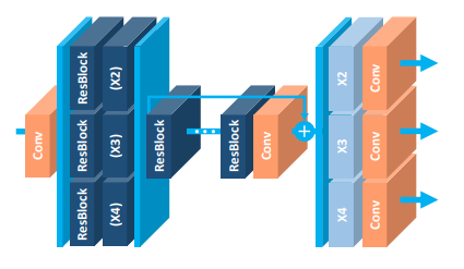
,(我从https://arxiv.org/abs/1707.02921那里拿来的)
它读起来真的很好。我想知道是否有模块化的积木可以画出这类数字?或者,如果一个人需要对TikZ非常胜任,而且没有捷径可供选择。(如果防御得当,我愿意接受TikZ以外的其他替代方案)
编辑:正如我所说的,我正在寻找TikZ中的模块块和示例语法来创建堆叠的3D块,这并不是一个完美的代码,可以精确地构建附加的图形(尽管这将是不可思议的)。
回答 1
Stack Overflow用户
回答已采纳
发布于 2018-05-04 16:46:48
对于我所有的"3D tikz绘图“,我一直在使用来自这个tikz例子的并行化形状。由此,你可以建立基本的三维形状,任何颜色,大小等。
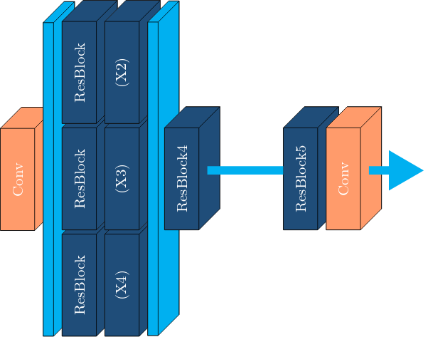
我在您的示例上的最初工作(这是我在overleaf.com上使用的确切代码)和相应的图像如下。要达到完全相同的效果还需要做大量的工作(中间块上方的箭头,再加上符号,两边的不同颜色,文本字体等等)。
\documentclass[tikz]{standalone}

%% Language and font encodings
\usepackage[english]{babel}
\usepackage[utf8x]{inputenc}
\usepackage[T1]{fontenc}

\usepackage{xcolor}
\definecolor{darkblue}{HTML}{1f4e79}
\definecolor{lightblue}{HTML}{00b0f0}
\definecolor{salmon}{HTML}{ff9c6b}

\usetikzlibrary{backgrounds,calc,shadings,shapes.arrows,arrows,shapes.symbols,shadows,positioning,decorations.markings,backgrounds,arrows.meta}

% Define parallelepiped shape:
\makeatletter
\pgfkeys{/pgf/.cd,
  parallelepiped offset x/.initial=2mm,
  parallelepiped offset y/.initial=2mm
}
\pgfdeclareshape{parallelepiped}
{
  \inheritsavedanchors[from=rectangle] % this is nearly a rectangle
  \inheritanchorborder[from=rectangle]
  \inheritanchor[from=rectangle]{north}
  \inheritanchor[from=rectangle]{north west}
  \inheritanchor[from=rectangle]{north east}
  \inheritanchor[from=rectangle]{center}
  \inheritanchor[from=rectangle]{west}
  \inheritanchor[from=rectangle]{east}
  \inheritanchor[from=rectangle]{mid}
  \inheritanchor[from=rectangle]{mid west}
  \inheritanchor[from=rectangle]{mid east}
  \inheritanchor[from=rectangle]{base}
  \inheritanchor[from=rectangle]{base west}
  \inheritanchor[from=rectangle]{base east}
  \inheritanchor[from=rectangle]{south}
  \inheritanchor[from=rectangle]{south west}
  \inheritanchor[from=rectangle]{south east}
  \backgroundpath{
    % store lower right in xa/ya and upper right in xb/yb
    \southwest \pgf@xa=\pgf@x \pgf@ya=\pgf@y
    \northeast \pgf@xb=\pgf@x \pgf@yb=\pgf@y
    \pgfmathsetlength\pgfutil@tempdima{\pgfkeysvalueof{/pgf/parallelepiped
      offset x}}
    \pgfmathsetlength\pgfutil@tempdimb{\pgfkeysvalueof{/pgf/parallelepiped
      offset y}}
    \def\ppd@offset{\pgfpoint{\pgfutil@tempdima}{\pgfutil@tempdimb}}
    \pgfpathmoveto{\pgfqpoint{\pgf@xa}{\pgf@ya}}
    \pgfpathlineto{\pgfqpoint{\pgf@xb}{\pgf@ya}}
    \pgfpathlineto{\pgfqpoint{\pgf@xb}{\pgf@yb}}
    \pgfpathlineto{\pgfqpoint{\pgf@xa}{\pgf@yb}}
    \pgfpathclose
    \pgfpathmoveto{\pgfqpoint{\pgf@xb}{\pgf@ya}}
    \pgfpathlineto{\pgfpointadd{\pgfpoint{\pgf@xb}{\pgf@ya}}{\ppd@offset}}
    \pgfpathlineto{\pgfpointadd{\pgfpoint{\pgf@xb}{\pgf@yb}}{\ppd@offset}}
    \pgfpathlineto{\pgfpointadd{\pgfpoint{\pgf@xa}{\pgf@yb}}{\ppd@offset}}
    \pgfpathlineto{\pgfqpoint{\pgf@xa}{\pgf@yb}}
    \pgfpathmoveto{\pgfqpoint{\pgf@xb}{\pgf@yb}}
    \pgfpathlineto{\pgfpointadd{\pgfpoint{\pgf@xb}{\pgf@yb}}{\ppd@offset}}
  }
}
\makeatother

\tikzset{
  % Dark blue blocks
  block/.style={
    parallelepiped,fill=white, draw,
    minimum width=0.8cm,
    minimum height=2.4cm,
    parallelepiped offset x=0.5cm,
    parallelepiped offset y=0.5cm,
    path picture={
      \draw[top color=darkblue,bottom color=darkblue]
        (path picture bounding box.south west) rectangle
        (path picture bounding box.north east);
    },
    text=white,
  },
  % Orange-ish blocks
  conv/.style={
    parallelepiped,fill=white, draw,
    minimum width=0.8cm,
    minimum height=2.4cm,
    parallelepiped offset x=0.5cm,
    parallelepiped offset y=0.5cm,
    path picture={
      \draw[top color=salmon,bottom color=salmon]
        (path picture bounding box.south west) rectangle
        (path picture bounding box.north east);
    },
    text=white,
  },
  % Taller Light blue blocks:
  plate/.style={
    parallelepiped,fill=white, draw,
    minimum width=0.1cm,
    minimum height=7.4cm,
    parallelepiped offset x=0.5cm,
    parallelepiped offset y=0.5cm,
    path picture={
      \draw[top color=lightblue,bottom color=lightblue]
        (path picture bounding box.south west) rectangle
        (path picture bounding box.north east);
    },
    text=white,
  },
  % Arrows between blocks:
  link/.style={
    color=lightblue,
    line width=2mm,
  },
}

\begin{document}

\begin{tikzpicture}
  % The order of blocks matters since some are partially hidden behind subsequent blocks.
  \node[conv](conv1){\rotatebox{90}{Conv}};
  \node[plate,right=0.2cm of conv1](plate1){};
  % yshift to align the bottom of that blocks with the previous taller block.
  \node[block,right=0.2cm of plate1,yshift=-2.5cm](resblock1){\rotatebox{90}{ResBlock}};
  \node[block,above=0.1cm of resblock1](resblock2){\rotatebox{90}{ResBlock}};
  \node[block,above=0.1cm of resblock2](resblock3){\rotatebox{90}{ResBlock}};
  \node[block,right=0.2cm of resblock1](x1){\rotatebox{90}{(X4)}};
  \node[block,above=0.1cm of x1](x2){\rotatebox{90}{(X3)}};
  \node[block,above=0.1cm of x2](x3){\rotatebox{90}{(X2)}};
  \node[plate,right=0.2cm of x2](plate2){};
  \node[block,right=0.6cm of x2](resblock4){\rotatebox{90}{ResBlock4}};
  \node[block,right=2cm of resblock4](resblock5){\rotatebox{90}{ResBlock5}};
  \node[conv,right=0.2cm of resblock5](conv2){\rotatebox{90}{Conv}};
  \draw [-,link] ([xshift=0.2cm,yshift=0.2cm]resblock4.east) -- ([yshift=0.2cm]resblock5.west);
  \draw [-triangle 60,link] ([xshift=0.2cm,yshift=0.2cm]conv2.east) -- ([xshift=1.5cm,yshift=0.2cm]conv2.east);
\end{tikzpicture}

\end{document}页面原文内容由Stack Overflow提供。腾讯云小微IT领域专用引擎提供翻译支持
原文链接:
https://stackoverflow.com/questions/50131068
复制相关文章
相似问题
腾讯云开发者

Copyright © 2013 - 2026 Tencent Cloud. All Rights Reserved. 腾讯云 版权所有
深圳市腾讯计算机系统有限公司 ICP备案/许可证号:粤B2-20090059 ![]() 粤公网安备44030502008569号
粤公网安备44030502008569号
腾讯云计算(北京)有限责任公司 京ICP证150476号 | 京ICP备11018762号