
将角度定量数据转换为定性图像
我是一个结晶学家,试图分析晶体的方向,从多达5000份文件。Matlab可以转换如下表中的角值:
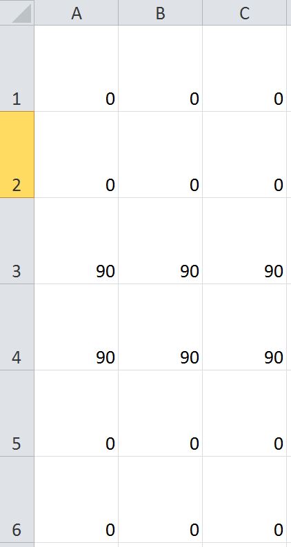
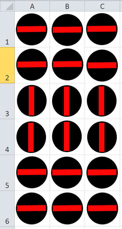
变成这样的桌子?:
回答 2
Stack Overflow用户
发布于 2014-10-15 18:34:42
这里有一个基于Lakesh的想法的更具体的例子。然而,这将处理任何数量的轮换。首先,从中间有条条的基本圆形图像开始。一旦这样做,只需运行一个for循环,它将所有这些旋转图像堆叠在一个网格中,该网格类似于我们在这个矩阵中看到的每个旋转角度的旋转值矩阵中所看到的角度。
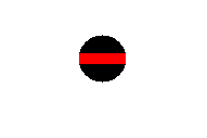
诀窍是找出如何定义基本方向图像。因此,让我们定义一个白色的正方形,中间是一个黑色的圆圈。我们还将在中间定义一条红线。现在,让我们假设基本方向图像是51x51。因此,我们可以这样做:
%// Define a grid of points between -25 to 25 for both X and Y
[X,Y] = meshgrid(-25:25,-25:25);

%// Define radius
radius = 22;

%// Generate a black circle that has the above radius
base_image = (X.^2 + Y.^2) <= radius^2;

%// Make into a 3 channel colour image
base_image = ~base_image;
base_image = 255*cast(repmat(base_image, [1 1 3]), 'uint8');

%// Place a strip in the middle of the circle that's red
width_strip = 44;
height_strip = 10;
strip_locs = (X >= -width_strip/2 & X <= width_strip/2 & Y >= -height_strip/2 & Y <= height_strip/2);
base_image(strip_locs) = 255;
有了以上这些,我得到的是:
现在,您需要做的就是创建一个最终的输出映像,它包含的图像与矩阵中的行和列一样多。考虑到旋转矩阵值存储在M中,我们可以从图像处理工具箱中使用imrotate,并指定'crop'标志,以确保输出图像与原始图像大小相同。但是,对于imrotate,在旋转图像后任何值都不会出现在图像中,它默认为0。你希望这个在你的例子中看起来是白色的,所以我们需要做一些工作。您需要做的是创建一个与输入图像大小相同的logical矩阵,然后像处理基本图像一样旋转它。无论哪个像素在这个旋转的白色图像中显示为黑色(也是false),这些都是我们需要设置为白色的值。因此:
%// Get size of rotation value matrix
[rows,cols] = size(M);

%// For storing the output image
output_image = zeros(rows*51, cols*51, 3);

%// For each value in our rotation value matrix...
for row = 1 : rows
    for col = 1 : cols
        %// Rotate the image
        rotated_image = imrotate(base_image, M(row,col), 'crop');

        %// Take a completely white image and rotate this as well.
        %// Invert so we know which values were outside of the image
        Mrot = ~imrotate(true(size(base_image)), M(row,col), 'crop');

        %// Set these values outside of each rotated image to white
        rotated_image(Mrot) = 255;

        %// Store in the right slot.
        output_image((row-1)*51 + 1 : row*51, (col-1)*51 + 1 : col*51, :) = rotated_image;
    end
end
让我们尝试几个角度,以确保这是正确的:
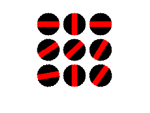
M = [0 90 180; 35 45 60; 190 270 55];有了上面的矩阵,这就是我的形象。它存储在output_image中
如果要将此映像保存到文件中,只需执行imwrite(output_image, 'output.png');,其中output.png是要保存到磁盘中的文件的名称。我之所以选择PNG,是因为它是无损的,与其他无损标准(保存JPEG 2000)相比,它的文件大小相对较低。
编辑以在角为0时不显示直线。
如果您希望使用上面的代码,您只希望在角度为0的情况下显示一个黑色圆圈,那么只需在if循环中插入一个for语句,也可以创建另一个图像,该图像包含一个不带条形的黑色圆圈。当if条件满足时,您可以将这个新图像放置在正确的网格位置,而不是使用红色条形的黑色圆圈。
因此,使用上面的代码作为基线进行如下操作:
%// Define matrix of sample angles
M = [0 90 180; 35 45 60; 190 270 55];

%// Define a grid of points between -25 to 25 for both X and Y
[X,Y] = meshgrid(-25:25,-25:25);

%// Define radius
radius = 22;

%// Generate a black circle that has the above radius
base_image = (X.^2 + Y.^2) <= radius^2;

%// Make into a 3 channel colour image
base_image = ~base_image;
base_image = 255*cast(repmat(base_image, [1 1 3]), 'uint8');

%// NEW - Create a black circle image without the red strip
black_circle = base_image;

%// Place a strip in the middle of the circle that's red
width_strip = 44;
height_strip = 10;
strip_locs = (X >= -width_strip/2 & X <= width_strip/2 & Y >= -height_strip/2 & Y <= height_strip/2);
base_image(strip_locs) = 255;

%// Get size of rotation value matrix
[rows,cols] = size(M);

%// For storing the output image
output_image = zeros(rows*51, cols*51, 3);

%// NEW - define tolerance
tol = 5;

%// For each value in our rotation value matrix...
for row = 1 : rows
    for col = 1 : cols

        %// NEW - If the angle is around 0, then draw a black circle only
        if M(row,col) >= -tol && M(row,col) <= tol
            rotated_image = black_circle;
        else %// This is the logic if the angle is not around 0
             %// Rotate the image
            rotated_image = imrotate(base_image, M(row,col), 'crop');

            %// Take a completely white image and rotate this as well.
            %// Invert so we know which values were outside of the image
            Mrot = ~imrotate(true(size(base_image)), M(row,col), 'crop');

            %// Set these values outside of each rotated image to white
            rotated_image(Mrot) = 255;
        end

         %// Store in the right slot.
        output_image((row-1)*51 + 1 : row*51, (col-1)*51 + 1 : col*51, :) = rotated_image;
    end
end上述代码中的变量tol定义了公差,其中-tol <= angle <= tol中的任何内容都绘制了黑色圆圈。这是为了允许在比较时允许浮点公差,因为直接使用浮点值执行相等操作从来都不是一个好主意。通常,人们接受的做法是在一定的容忍范围内比较你想要测试是否平等的地方。
使用上面修改的代码和前面示例中看到的角度M矩阵,我现在得到了这个图像:
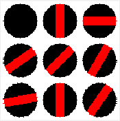
注意,矩阵的左上角有一个0的角度,因此它被可视化为一个黑色的圆圈,没有像我们期望的那样穿过它。
Stack Overflow用户
发布于 2014-10-15 18:06:16
解决你的问题的一般想法:
1. Store two images, 1 for 0 degrees and 180 degrees and another for 90 and 270 degrees.

2. Read the data from the file

3. if angle = 0 || angle == 180
      image = image1
   else
      image = image2
   end
处理任何角度:
1. Store one image. E.g image = imread('yourfile.png')
2. angle = Read the data from the file
3. B = imrotate(image,angle)https://stackoverflow.com/questions/26388718
复制相似问题
腾讯云开发者

Copyright © 2013 - 2026 Tencent Cloud. All Rights Reserved. 腾讯云 版权所有
深圳市腾讯计算机系统有限公司 ICP备案/许可证号:粤B2-20090059 ![]() 粤公网安备44030502008569号
粤公网安备44030502008569号
腾讯云计算(北京)有限责任公司 京ICP证150476号 | 京ICP备11018762号