
基于SPI位敲的Arduino多路模拟数字转换器
我正在使用一个纳米Arduino (ATMega 328)与两个基于这段代码的12位MCP3208模数转换器芯片进行通信。我有另一个设备(LED驱动程序TLC5940)被绑在这个页面上的引脚上,但是由于我使用的是位敲击,所以我使用的引脚应该不重要。因此,我的配置与上面的示例相同,只是:
    For ADC 1:
    CLK -> Arduino D6
    DOUT (MISO) -> Arduino D5
    DIN (MOSI) -> Arduino D12
    SS -> Arduino D7

    For ADC 2:
    CLK -> Arduino D6
    DOUT (MISO) -> Arduino D5
    DIN (MOSI) -> Arduino D12
    SS -> Arduino D8
所以,问题是我从ADC 1得到数据,而不是从ADC 2得到数据。我应该能够通过将选择引脚拉低来选择ADC 2,但我得到的只是0。有16个光电二极管连接到4个TLC2274运算放大器上.以下是Arduino代码:
//Scott Little, BrainGoggles, 2013, GNU GPL v3
#include <SoftwareSerial.h>
#include "Tlc5940.h"
SoftwareSerial bluetooth(4,2);  //TX 4, RX 2

#define SELPIN 7 //Selection Pin for 1st ADC
#define SELPIN2 8 //Selection Pin for 2nd ADC
#define DATAOUT 12//MOSI
#define DATAIN  5//MISO
#define SPICLOCK  6//Clock
int readvalue;
byte readvaluearray[32];
int intensity = 0;

void setup()
{
  /* Call Tlc.init() to setup the tlc.
     You can optionally pass an initial PWM value (0 - 4095) for all channels.*/
  Tlc.init();  //interferes with other SPI
  Tlc.clear();  //set pin modes

  pinMode(SELPIN, OUTPUT); //adc 1 selection pin
  pinMode(SELPIN2, OUTPUT); //adc 2 selection pin
  pinMode(DATAOUT, OUTPUT);
  pinMode(DATAIN, INPUT);
  pinMode(SPICLOCK, OUTPUT);
  //disable devices to start with
  digitalWrite(SELPIN,HIGH);
  digitalWrite(SELPIN2,HIGH);
  digitalWrite(DATAOUT,LOW);
  digitalWrite(SPICLOCK,LOW);
  bluetooth.begin(9600);
  Serial.begin(9600);

}

void loop()
{
  if (bluetooth.available()) // Wait until a character is received
  {
    char val = (char)bluetooth.read();
    Serial.println(val);

    switch(val) // Perform an action depending on the command
    {
      case 't'://increase intensity when an 'e' is received
    intensity = plus(intensity);
      break;

      case 'y'://decrease intensity when an 'r' is received
    intensity = minus(intensity);
      break;

      case 'q'://turn the light on when a 'q' is received
    on();
      break;

      case 'w'://turn the light off when a 'w' is received
    off();
      break;
    }
  }

  for (int i=0; i<8; i++){        //read from ADC 1
    readvalue = read_adc(i+1);
    readvaluearray[2*i] = highByte(readvalue);
    readvaluearray[2*i+1] = lowByte(readvalue);
  }

  for (int i=8; i<16; i++){        //read from ADC 2
    readvalue = read_adc2(i-7);
    readvaluearray[2*i] = highByte(readvalue);
    readvaluearray[2*i+1] = lowByte(readvalue);
  }

  bluetooth.write(readvaluearray,32);
  Serial.println("new");
  for (int i=0;i<16;i++){
    Serial.println(word(readvaluearray[2*i],readvaluearray[2*i+1]));
  }

  delay(2000);
}


int read_adc(int channel){
  int adcvalue = 0;
  byte commandbits = B11000000; //command bits - start, mode, chn (3), dont care (3)

  //allow channel selection
  commandbits|=((channel-1)<<3);

  digitalWrite(SELPIN,LOW); //Select adc

  // setup bits to be written
  for (int i=7; i>=3; i--){
    digitalWrite(DATAOUT,commandbits&1<<i);
    //cycle clock
    digitalWrite(SPICLOCK,HIGH);
    digitalWrite(SPICLOCK,LOW);
  }

  digitalWrite(SPICLOCK,HIGH);    //ignores 2 null bits
  digitalWrite(SPICLOCK,LOW);
  digitalWrite(SPICLOCK,HIGH);
  digitalWrite(SPICLOCK,LOW);

  //read bits from adc
  for (int i=11; i>=0; i--){
    adcvalue+=digitalRead(DATAIN)<<i;
    //cycle clock
    digitalWrite(SPICLOCK,HIGH);
    digitalWrite(SPICLOCK,LOW);
  }
  digitalWrite(SELPIN, HIGH); //turn off device

  return adcvalue;
}

int read_adc2(int channel){
  int adcvalue = 0;
  byte commandbits = B11000000; //command bits - start, mode, chn (3), dont care (3)

  //allow channel selection
  commandbits|=((channel-1)<<3);

  digitalWrite(SELPIN2,LOW); //Select adc

  // setup bits to be written
  for (int i=7; i>=3; i--){
    digitalWrite(DATAOUT,commandbits&1<<i);
    //cycle clock
    digitalWrite(SPICLOCK,HIGH);
    digitalWrite(SPICLOCK,LOW);
  }

  digitalWrite(SPICLOCK,HIGH);    //ignores 2 null bits
  digitalWrite(SPICLOCK,LOW);
  digitalWrite(SPICLOCK,HIGH);
  digitalWrite(SPICLOCK,LOW);

  //read bits from adc
  for (int i=11; i>=0; i--){
    adcvalue+=digitalRead(DATAIN)<<i;
    //cycle clock
    digitalWrite(SPICLOCK,HIGH);
    digitalWrite(SPICLOCK,LOW);
  }
  digitalWrite(SELPIN2, HIGH); //turn off device

  return adcvalue;
}

void on(void)
{
  Tlc.set(1, 4095);  //set pin 5 to max brightness
  Tlc.update();  //execute set
  //bluetooth.println("on");
  //Serial.println("on");
}

void off(void)
{
  Tlc.set(1, 0);  //set pin 5 to min brightness
  Tlc.update();  //execute set
  //bluetooth.println("off");
  //Serial.println("off");
}

int plus(int value)
{
  value = value + 64;
  if (value > 4095){value = 4095;}
  Tlc.set(1, value);  //set pin 5 to min brightness
  Tlc.update();  //execute set
  Serial.println(value);
  return value;
}

int minus(int value)
{
  value = value - 64;
  if (value < 0){value = 0;}
  Tlc.set(1, value);  //set pin 5 to min brightness
  Tlc.update();  //execute set
  Serial.println(value);
  return value;
}
下面是我得到的示例输出:
new
374
372
311
313
356
276
337
387
0
0
0
0
0
0
0
0回答 2
Stack Overflow用户
发布于 2013-11-26 07:07:55
现在起作用了。我物理地将ADC上对应于DOUT (ADC 12)的引脚更改为与MISO (Arduino 12)对应的Arduino上的引脚,并将代码更改如下:
#define DATAOUT 5  //MOSI
#define DATAIN  12 //MISO
它应该像我以前的工作,因为我有点敲打,但它似乎现在工作,因为米索是在“正确的”别针。
Stack Overflow用户
发布于 2016-08-22 16:57:28
我设计了一个草图,用于驾驶10 (或更多) RGB LED与TLC5940在我的Arduino uno。这也可能适用于纳米。我是驱动10个共阳极rgb leds在30个通道与两个two 5940的雏菊在一起。只要您配置您正在使用的多少TLC5940芯片,我们就可以实现更多的目标。这适用于12位占空比控制(0 - 4095)。
- 在arduino IDE中,您必须从这里导入Paul的TLC5940库:https://github.com/PaulStoffregen/Tlc5940。
- 编辑tlc_config.h文件,其中NUM_TLCs应该等于2(默认为1): “#定义NUM_TLCS 2”
- 现在我们可以看一下草图来运行这个东西
这是草图的连线:
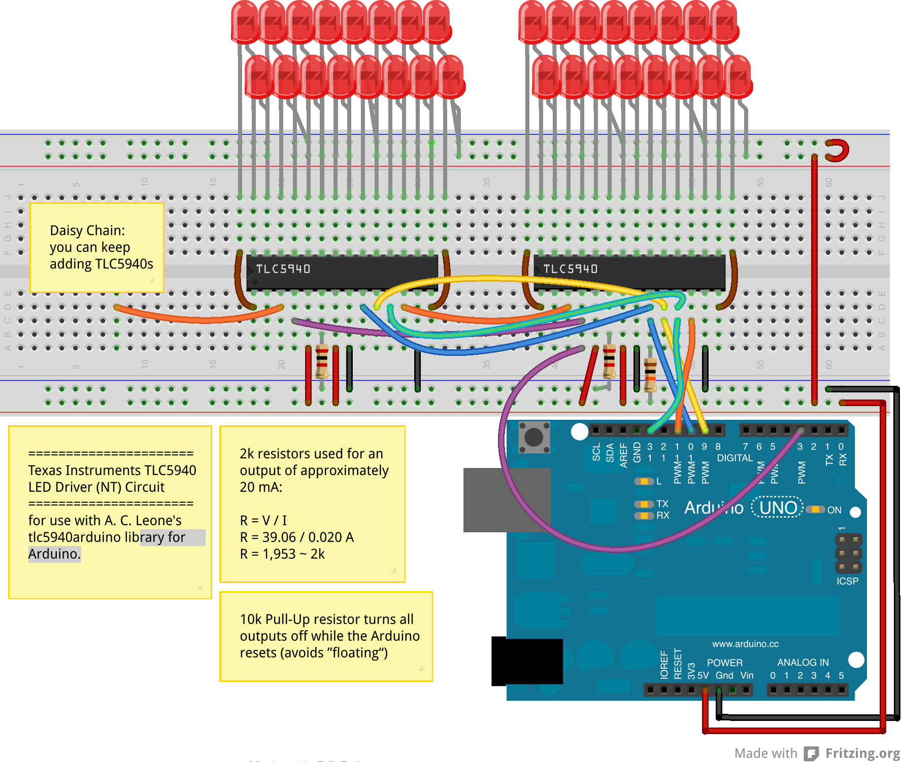
虽然这描绘了单色leds,我将映射我的rgb引脚0-2,3-5,6-8,9-11……等等。
代码:
#include "Tlc5940.h"
int rgbChannels = 30;//total channels used one the TLC5940's
int rgb[30]; ///should be the same as the number of channels
int rgbLights = 10;/// this is the number of rgb leds possible on 2 TLC5940's but you could always daisy chain more...
int colorArray[10];//this sets the number of colors to use (one per rgb led)
void setup() {
// put your setup code here, to run once
Tlc.init(0); // Initiates the TLC5940 and set all channels off
Serial.begin(250000);
Serial.println("Total Channels: " + String(rgbChannels) + " Total
RGB Ligts: " + String(rgbLights));
float divisor = 360 / (rgbChannels / 3); //degrees of color to
display divided by the number of rgb lights
Serial.println("Divisor: " + String(divisor) );
float Step = divisor;
for (int i = 0; i < rgbLights; i++) {
colorArray[i] = Step;
Serial.println("colorArray[" + String(i) + "]: " + String(colorArray[i]));
Step = Step + divisor;
}
}
void ledColor(int channel, int red, int green, int blue)
{
Tlc.set(channel, red);
Tlc.set(channel + 1, green);
Tlc.set(channel + 2, blue);
}
///convert hsi color to rgb
void hsi_to_rgb(int startChannel, float H, float S, float I) {
int r, g, b;
if (H > 360) {
H = H - 360;
}
// Serial.println("H: "+String(H));
H = fmod(H, 360); // cycle H around to 0-360 degrees
H = 3.14159 * H / (float)180; // Convert to radians.
S = S > 0 ? (S < 1 ? S : 1) : 0; // clamp S and I to interval [0,1]
I = I > 0 ? (I < 1 ? I : 1) : 0;
if (H < 2.09439) {
r = 4095 * I / 3 * (1 + S * cos(H) / cos(1.047196667 - H));
g = 4095 * I / 3 * (1 + S * (1 - cos(H) / cos(1.047196667 - H)));
b = 4095 * I / 3 * (1 - S);
} else if (H < 4.188787) {
H = H - 2.09439;
g = 4095 * I / 3 * (1 + S * cos(H) / cos(1.047196667 - H));
b = 4095 * I / 3 * (1 + S * (1 - cos(H) / cos(1.047196667 - H)));
r = 4095 * I / 3 * (1 - S);
} else {
H = H - 4.188787;
b = 4095 * I / 3 * (1 + S * cos(H) / cos(1.047196667 - H));
r = 4095 * I / 3 * (1 + S * (1 - cos(H) / cos(1.047196667 - H)));
g = 4095 * I / 3 * (1 - S);
}
rgb[0 + startChannel] = r;
rgb[1 + startChannel] = g;
rgb[2 + startChannel] = b;
}
void rainbowShift() {
float brightness = .4;
float saturation = 1;
for (int n = 0; n <= 360; n++) {
for (int i = 0, j = 0; i < rgbLights; i++) {
hsi_to_rgb(j, colorArray[i] + n, saturation, brightness);
//Serial.println("rgb"+String(i)+":"+String(rgb[j])+","+String(rgb[j+1])+","+String(rgb[j+2]));
ledColor(j, rgb[j], rgb[j + 1], rgb[j + 2]);
j = j + 3;
}
Tlc.update();
Tlc.clear();
delayMicroseconds(500);
}
}
void loop() {
// put your main code here, to run repeatedly:
rainbowShift();////perform the function a few times
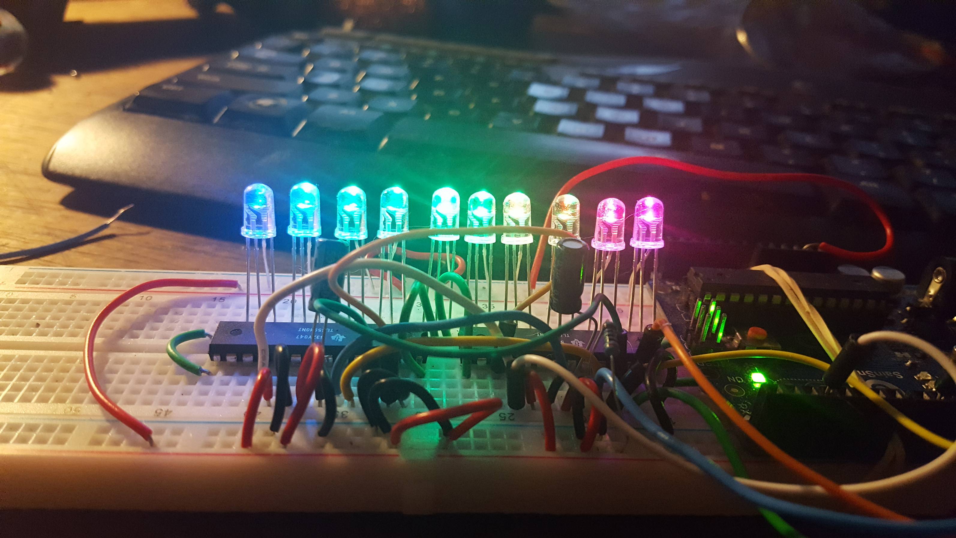
}当所有的事情完成后,你的RGB发光二极管上就会出现一条彩色的彩虹。
看看这段视频:
<iframe width="560" height="315" src="https://www.youtube.com/embed/CWdL9i8U8U0" frameborder="0" allowfullscreen></iframe>
下面是结果的图像:
https://stackoverflow.com/questions/19887409
复制相似问题
腾讯云开发者

Copyright © 2013 - 2026 Tencent Cloud. All Rights Reserved. 腾讯云 版权所有
深圳市腾讯计算机系统有限公司 ICP备案/许可证号:粤B2-20090059 ![]() 粤公网安备44030502008569号
粤公网安备44030502008569号
腾讯云计算(北京)有限责任公司 京ICP证150476号 | 京ICP备11018762号