
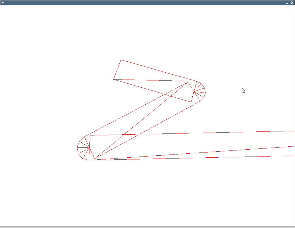
多边形轮廓线上的边并不总是正确的
我使用下面的算法生成四边形,然后呈现成这样的轮廓
http://img810.imageshack.us/img810/8530/uhohz.png
在图像上看到的问题是,有时线条太薄,而它们应该总是相同的宽度。我的算法找到了第一个顶点的4顶点,然后下一个顶点的上2顶点是前一个顶点的下2。这创造了连接的线路,但它似乎并不总是有效的。我怎么才能解决这个问题?
这是我的算法:
 void OGLENGINEFUNCTIONS::GenerateLinePoly(const std::vector<std::vector<GLdouble>> &input,
                          std::vector<GLfloat> &output, int width)
 {
     output.clear();

     if(input.size() < 2)
     {
         return;
     }

     int temp;
     float dirlen;
     float perplen;
     POINTFLOAT start;
     POINTFLOAT end;
     POINTFLOAT dir;
     POINTFLOAT ndir;
     POINTFLOAT perp;
     POINTFLOAT nperp;

     POINTFLOAT perpoffset;
     POINTFLOAT diroffset;

     POINTFLOAT p0, p1, p2, p3;

     for(unsigned int i = 0; i < input.size() - 1; ++i)
     {

         start.x = static_cast<float>(input[i][0]);
         start.y = static_cast<float>(input[i][1]);

         end.x = static_cast<float>(input[i + 1][0]);
         end.y = static_cast<float>(input[i + 1][1]);

         dir.x = end.x - start.x;
         dir.y = end.y - start.y;

         dirlen = sqrt((dir.x * dir.x) + (dir.y * dir.y));

         ndir.x = static_cast<float>(dir.x * 1.0 / dirlen);
         ndir.y = static_cast<float>(dir.y * 1.0 / dirlen);

         perp.x = dir.y;
         perp.y = -dir.x;

         perplen = sqrt((perp.x * perp.x) + (perp.y * perp.y));

         nperp.x = static_cast<float>(perp.x * 1.0 / perplen);
         nperp.y = static_cast<float>(perp.y * 1.0 / perplen);

         perpoffset.x = static_cast<float>(nperp.x * width * 0.5);
         perpoffset.y = static_cast<float>(nperp.y * width * 0.5);

         diroffset.x = static_cast<float>(ndir.x * 0 * 0.5);
         diroffset.y = static_cast<float>(ndir.y * 0 * 0.5);

            // p0 = start + perpoffset - diroffset
            // p1 = start - perpoffset - diroffset
            // p2 = end + perpoffset + diroffset
            // p3 = end - perpoffset + diroffset

         p0.x = start.x + perpoffset.x - diroffset.x;
         p0.y = start.y + perpoffset.y - diroffset.y;

         p1.x = start.x - perpoffset.x - diroffset.x;
         p1.y = start.y - perpoffset.y - diroffset.y;

         if(i > 0)
         {
             temp = (8 * (i - 1));
             p2.x = output[temp + 2];
             p2.y = output[temp + 3];
             p3.x = output[temp + 4];
             p3.y = output[temp + 5];

         }
         else
         {
             p2.x = end.x + perpoffset.x + diroffset.x;
             p2.y = end.y + perpoffset.y + diroffset.y;

             p3.x = end.x - perpoffset.x + diroffset.x;
             p3.y = end.y - perpoffset.y + diroffset.y;
         }


         output.push_back(p2.x);
         output.push_back(p2.y);
         output.push_back(p0.x);
         output.push_back(p0.y);
         output.push_back(p1.x);
         output.push_back(p1.y);
         output.push_back(p3.x);
         output.push_back(p3.y);

     }
 }
编辑:
 POINTFLOAT multiply(const POINTFLOAT &a, float b)
 {
     POINTFLOAT result;
     result.x = a.x * b;
     result.y = a.y * b;
     return result;
 }

 POINTFLOAT normalize(const POINTFLOAT &a)
 {
     return multiply(a, 1.0f / sqrt(a.x * a.x + a.y * a.y));
 }


 POINTFLOAT slerp2d( const POINTFLOAT v0,
                     const POINTFLOAT v1, float t )
 {
     float dot = (v0.x * v1.x + v1.y * v1.y);
     if( dot < -1.0f ) dot = -1.0f;
     if( dot > 1.0f ) dot = 1.0f;

     float theta_0 = acos( dot );
     float theta = theta_0 * t;

     POINTFLOAT v2;
     v2.x = -v0.y;
     v2.y = v0.x;

     POINTFLOAT result;
     result.x = v0.x * cos(theta) + v2.x * sin(theta);
     result.y = v0.y * cos(theta) + v2.y * sin(theta);

     return result;
 }

 void OGLENGINEFUNCTIONS::GenerateLinePoly(const std::vector<std::vector<GLdouble> > &input,
                          std::vector<GLfloat> &output, int width)
 {
     output.clear();

     if(input.size() < 2)
     {
         return;
     }

     float w = width / 2.0f;

     //glBegin(GL_TRIANGLES);
     for( size_t i = 0; i < input.size()-1; ++i )
     {
         POINTFLOAT cur;
         cur.x = input[i][0];
         cur.y = input[i][1];


         POINTFLOAT nxt;
         nxt.x = input[i+1][0];
         nxt.y = input[i+1][1];

         POINTFLOAT b;
         b.x = nxt.x - cur.x;
         b.y = nxt.y - cur.y;

         b = normalize(b);


         POINTFLOAT b_perp;
         b_perp.x = -b.y;
         b_perp.y = b.x;


         POINTFLOAT p0;
         POINTFLOAT p1;
         POINTFLOAT p2;
         POINTFLOAT p3;

         p0.x = cur.x + b_perp.x * w;
         p0.y = cur.y + b_perp.y * w;

         p1.x = cur.x - b_perp.x * w;
         p1.y = cur.y - b_perp.y * w;

         p2.x = nxt.x + b_perp.x * w;
         p2.y = nxt.y + b_perp.y * w;

         p3.x = nxt.x - b_perp.x * w;
         p3.y = nxt.y - b_perp.y * w;

         output.push_back(p0.x);
         output.push_back(p0.y);
         output.push_back(p1.x);
         output.push_back(p1.y);
         output.push_back(p2.x);
         output.push_back(p2.y);

         output.push_back(p2.x);
         output.push_back(p2.y);
         output.push_back(p1.x);
         output.push_back(p1.y);
         output.push_back(p3.x);
         output.push_back(p3.y);


         // only do joins when we have a prv
         if( i == 0 ) continue;

         POINTFLOAT prv;
         prv.x = input[i-1][0];
         prv.y = input[i-1][1];

         POINTFLOAT a;
         a.x = prv.x - cur.x;
         a.y = prv.y - cur.y;

         a = normalize(a);

         POINTFLOAT a_perp;
         a_perp.x = a.y;
         a_perp.y = -a.x;

         float det = a.x * b.y - b.x * a.y;
         if( det > 0 )
         {
             a_perp.x = -a_perp.x;
             a_perp.y = -a_perp.y;

             b_perp.x = -b_perp.x;
             b_perp.y = -b_perp.y;
         }

         // TODO: do inner miter calculation

         // flip around normals and calculate round join points
         a_perp.x = -a_perp.x;
         a_perp.y = -a_perp.y;

         b_perp.x = -b_perp.x;
         b_perp.y = -b_perp.y;

         size_t num_pts = 4;

         std::vector< POINTFLOAT> round( 1 + num_pts + 1 );
         POINTFLOAT nc;
         nc.x = cur.x + (a_perp.x * w);
         nc.y = cur.y + (a_perp.y * w);

         round.front() = nc;

         nc.x = cur.x + (b_perp.x * w);
         nc.y = cur.y + (b_perp.y * w);

         round.back() = nc;

         for( size_t j = 1; j < num_pts+1; ++j )
         {
             float t = (float)j / (float)(num_pts + 1);
             if( det > 0 )
             {
                 POINTFLOAT nin;
                 nin = slerp2d( b_perp, a_perp, 1.0f-t );
                 nin.x *= w;
                 nin.y *= w;

                 nin.x += cur.x;
                 nin.y += cur.y;

                 round[j] = nin;
             }
             else
             {
                 POINTFLOAT nin;
                 nin = slerp2d( a_perp, b_perp, t );
                 nin.x *= w;
                 nin.y *= w;

                 nin.x += cur.x;
                 nin.y += cur.y;

                 round[j] = nin;
             }
         }

         for( size_t j = 0; j < round.size()-1; ++j )
         {

             output.push_back(cur.x);
             output.push_back(cur.y);

             if( det > 0 )
             {
                 output.push_back(round[j + 1].x);
                 output.push_back(round[j + 1].y);
                 output.push_back(round[j].x);
                 output.push_back(round[j].y);
             }
             else
             {

                 output.push_back(round[j].x);
                 output.push_back(round[j].y);

                 output.push_back(round[j + 1].x);
                 output.push_back(round[j + 1].y);
             }
         }
     }
}回答 5
Stack Overflow用户
发布于 2010-06-17 04:58:43
需要编写本征,但是核心操作应该很容易映射到您使用的任何向量类。
// v0 and v1 are normalized
// t can vary between 0 and 1
// http://number-none.com/product/Understanding%20Slerp,%20Then%20Not%20Using%20It/
Vector2f slerp2d( const Vector2f& v0, const Vector2f& v1, float t )
{
    float dot = v0.dot(v1);
    if( dot < -1.0f ) dot = -1.0f;
    if( dot > 1.0f ) dot = 1.0f;

    float theta_0 = acos( dot );
    float theta = theta_0 * t;

    Vector2f v2( -v0.y(), v0.x() );

    return ( v0*cos(theta) + v2*sin(theta) );
}


void glPolyline( const vector<Vector2f>& polyline, float width )
{
    if( polyline.size() < 2 ) return;
    float w = width / 2.0f;

    glBegin(GL_TRIANGLES);
    for( size_t i = 0; i < polyline.size()-1; ++i )
    {
        const Vector2f& cur = polyline[ i ];
        const Vector2f& nxt = polyline[i+1];

        Vector2f b = (nxt - cur).normalized();
        Vector2f b_perp( -b.y(), b.x() );

        Vector2f p0( cur + b_perp*w );
        Vector2f p1( cur - b_perp*w );
        Vector2f p2( nxt + b_perp*w );
        Vector2f p3( nxt - b_perp*w );

        // first triangle
        glVertex2fv( p0.data() );
        glVertex2fv( p1.data() );
        glVertex2fv( p2.data() );
        // second triangle
        glVertex2fv( p2.data() );
        glVertex2fv( p1.data() );
        glVertex2fv( p3.data() );

        // only do joins when we have a prv
        if( i == 0 ) continue;

        const Vector2f& prv = polyline[i-1];
        Vector2f a = (prv - cur).normalized();
        Vector2f a_perp( a.y(), -a.x() );

        float det = a.x()*b.y() - b.x()*a.y();
        if( det > 0 )
        {
            a_perp = -a_perp;
            b_perp = -b_perp;
        }

        // TODO: do inner miter calculation

        // flip around normals and calculate round join points
        a_perp = -a_perp;
        b_perp = -b_perp;

        size_t num_pts = 4;
        vector< Vector2f > round( 1 + num_pts + 1 );
        for( size_t j = 0; j <= num_pts+1; ++j )
        {
            float t = (float)j/(float)(num_pts+1);
            if( det > 0 )
                round[j] = cur + (slerp2d( b_perp, a_perp, 1.0f-t ) * w);
            else
                round[j] = cur + (slerp2d( a_perp, b_perp, t ) * w);
        }

        for( size_t j = 0; j < round.size()-1; ++j )
        {
            glVertex2fv( cur.data() );
            if( det > 0 )
            {
                glVertex2fv( round[j+1].data() );
                glVertex2fv( round[j+0].data() );
            }
            else
            {
                glVertex2fv( round[j+0].data() );
                glVertex2fv( round[j+1].data() );
            }
        }
    }
    glEnd();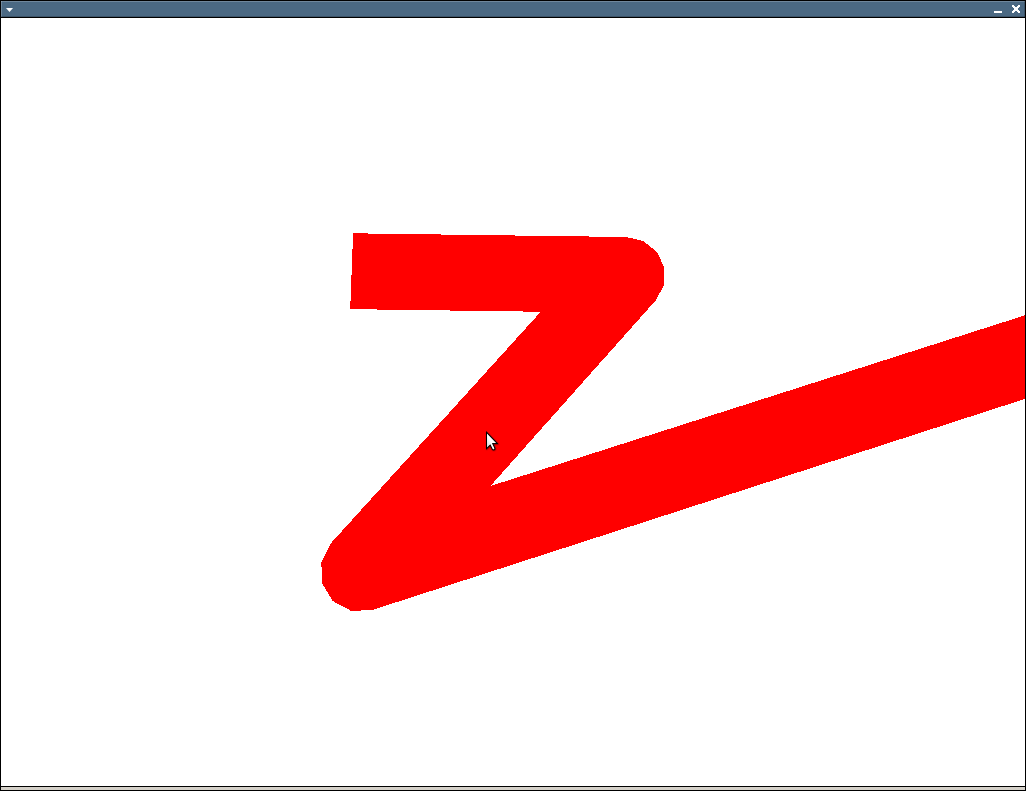
}编辑:截图:
Stack Overflow用户
发布于 2010-06-14 22:33:09
那麽:
- 把每一条线画到拐角处
- 在与角垂直的每个角处画一条额外的线。
如下所示:
alt文本http://www.geekops.co.uk/photos/0000-00-02%20%28Forum%20images%29/CorrectAngleDrawing.png
蓝色/红色代表你想连接的两条线。虚线绿色是你为使拐角处光滑而加的额外的一个。上面的图片显示,内容将被剪裁非常轻微的锐角。如果这是个问题,你可以把这两条连接线进一步向外延伸,然后把额外的线画得更远。
编辑我发现了我的建议中的一个缺陷。你在那里有一些凹的部分,它们根本不能正常工作。在这种情况下,你会想做一些事情,比如画一个倒角的边缘,而不是:
alt文本http://www.geekops.co.uk/photos/0000-00-02%20%28Forum%20images%29/CorrectAngleDrawing2.png
Edit2我已经对我之前发布的代码做了一些调试。下列各点应更有用处:
    // PolygonOutlineGen.cpp : A small program to calculate 4-point polygons
// to surround an input polygon.

#include <vector>
#include <math.h>
#include <iostream>
#include <iomanip>

using namespace std;

// Describe some structures etc. so the code will compile without
// requiring the GL libraries.
typedef double GLdouble;
typedef float GLfloat;
typedef struct POINTFLOAT
{
    float x;
    float y;
} POINTFLOAT;

// A function to generate two coordinates representing the start and end
// of a line perpendicular to start/end, offset by 'width' units.
void GenerateOffsetLineCoords(
    POINTFLOAT start,
    POINTFLOAT end,
    int width,
    POINTFLOAT& perpStart,
    POINTFLOAT& perpEnd)
{
    float dirlen;
    POINTFLOAT dir;
    POINTFLOAT ndir;
    POINTFLOAT nperp;
    POINTFLOAT perpoffset;

    // Work out the offset for a parallel line which is space outwards by 'width' units
    dir.x = end.x - start.x;
    dir.y = end.y - start.y;
    dirlen = sqrt((dir.x * dir.x) + (dir.y * dir.y));
    ndir.x = static_cast<float>(dir.x * 1.0 / dirlen);
    ndir.y = static_cast<float>(dir.y * 1.0 / dirlen);
    nperp.x = -ndir.y;
    nperp.y = ndir.x;
    perpoffset.x = static_cast<float>(nperp.x * width);
    perpoffset.y = static_cast<float>(nperp.y * width);

    // Calculate the offset coordinates for the new line
    perpStart.x = start.x + perpoffset.x;
    perpStart.y = start.y + perpoffset.y;
    perpEnd.x = end.x + perpoffset.x;
    perpEnd.y = end.y + perpoffset.y;
}

// Function to generate quads of coordinate pairs to surround the 'input'
// polygon.
void GenerateLinePoly(const std::vector<std::vector<GLdouble>> &input,
    std::vector<GLfloat> &output, int width)
{
    // Make sure we have something to produce an outline for and that it's not contaminated with previous results
    output.clear();
    if(input.size() < 2)
    {
        return;
    }

    // Storage for the pairs of lines which form sections of the outline
    POINTFLOAT line1_start;
    POINTFLOAT line1_end;
    POINTFLOAT line2_start;
    POINTFLOAT line2_end;

    // Storage for the outer edges of the quads we'll be generating
    POINTFLOAT line1offset_start;
    POINTFLOAT line1offset_end;
    POINTFLOAT line2offset_start;
    POINTFLOAT line2offset_end;

    // Storage for the line we'll use to make smooth joints between polygon sections.
    POINTFLOAT joininglineoffset_start;
    POINTFLOAT joininglineoffset_end;

    for(unsigned int i = 0; i < input.size() - 2; ++i)
    {
        // Grab the raw line input for the first line or if we've already done one, just re-use the last results
        if( i == 0 )
        {
            line1_start.x = static_cast<float>(input[i][0]);
            line1_start.y = static_cast<float>(input[i][1]);
            line1_end.x = static_cast<float>(input[i + 1][0]);
            line1_end.y = static_cast<float>(input[i + 1][1]);

            GenerateOffsetLineCoords(line1_start, line1_end, width, line1offset_start, line1offset_end);
        }
        else
        {
            line1_start = line2_start;
            line1offset_start = line2offset_start;
            line1_end = line2_end;
            line1offset_end = line2offset_end;
        }

        // Grab the second line and work out the coords of it's offset
        line2_start.x = static_cast<float>(input[i+1][0]);
        line2_start.y = static_cast<float>(input[i+1][1]);
        line2_end.x = static_cast<float>(input[i+2][0]);
        line2_end.y = static_cast<float>(input[i+2][1]);
        GenerateOffsetLineCoords(line2_start, line2_end, width, line2offset_start, line2offset_end);

        // Grab the offset for the line which joins the open end
        GenerateOffsetLineCoords(line2offset_start, line1offset_end, width, joininglineoffset_start, joininglineoffset_end);

        // Push line 1 onto the output
        output.push_back(line1_start.x);
        output.push_back(line1_start.y);
        output.push_back(line1_end.x);
        output.push_back(line1_end.y);
        output.push_back(line1offset_end.x);
        output.push_back(line1offset_end.y);
        output.push_back(line1offset_start.x);
        output.push_back(line1offset_start.y);

        // Push the new section onto the output
        output.push_back(line1offset_end.x);
        output.push_back(line1offset_end.y);
        output.push_back(line2offset_start.x);
        output.push_back(line2offset_start.y);
        output.push_back(joininglineoffset_start.x);
        output.push_back(joininglineoffset_start.y);
        output.push_back(joininglineoffset_end.x);
        output.push_back(joininglineoffset_end.y);
    }

    // TODO: Push the remaining line 2 on.

    // TODO: Add one last joining piece between the end and the beginning.
}

int main(int argc, char* argv[])
{
    // Describe some input data
    std::vector<std::vector<GLdouble>> input;
    std::vector<GLdouble> val1; val1.push_back(010.0); val1.push_back(010.0); input.push_back(val1);
    std::vector<GLdouble> val2; val2.push_back(050.0); val2.push_back(100.0); input.push_back(val2);
    std::vector<GLdouble> val3; val3.push_back(100.0); val3.push_back(100.0); input.push_back(val3);
    std::vector<GLdouble> val4; val4.push_back(010.0); val4.push_back(010.0); input.push_back(val4);

    // Generate the quads required to outline the shape
    std::vector<GLfloat> output;
    GenerateLinePoly(input, output, 5);

    // Dump the output as pairs of coordinates, grouped into the quads they describe
    cout << setiosflags(ios::fixed) << setprecision(1);
    for(unsigned int i=0; i < output.size(); i++)
    {
       if( (i > 0) && ((i)%2==0) ) { cout << endl; }
       if( (i > 0) && ((i)%8==0) ) { cout << endl; }
       cout << setw(7) << output[i];
    }
    cout << endl;
    return 0;
}
据我所知,..which看起来适用于凸多边形:-)
Stack Overflow用户
发布于 2010-06-14 17:28:29
啊,我现在明白了。这是因为你重复使用你的旧顶点,这些顶点不一定与你的新顶点平行。
只需用一个简单的例子来看你的代码,在这里你的输入点会有一个90度的急转弯。旧的顶点将与dir平行,而新的顶点将垂直。如果你在线上有足够近的点,那么你就会得到像你在照片中看到的奇怪的行为。
获得均匀宽度线没有“简单”的解决方案,但如果您一次将线条呈现成一对(即去掉i > 0大小写),情况会更好。这会给你一些丑陋的锐角,但你不会得到任何细线。
https://stackoverflow.com/questions/3039026
复制相似问题
腾讯云开发者

Copyright © 2013 - 2026 Tencent Cloud. All Rights Reserved. 腾讯云 版权所有
深圳市腾讯计算机系统有限公司 ICP备案/许可证号:粤B2-20090059 ![]() 粤公网安备44030502008569号
粤公网安备44030502008569号
腾讯云计算(北京)有限责任公司 京ICP证150476号 | 京ICP备11018762号