
Latex /Pgf用参数声明形状,用数字表示锚
我正在用pgf编写一些形状,我并不知道这是如何工作的,但是我成功地通过了文档。
\pgfdeclareshape{reg}{
  % The 'minimum width' and 'minimum height' keys, not the content, determine
  % the size
  \savedanchor\northeast{%
    \pgfmathsetlength\pgf@x{\pgfshapeminwidth}%
    \pgfmathsetlength\pgf@y{\pgfshapeminheight}%
    \pgf@x=0.11\pgf@x
    \pgf@y=0.15\pgf@y
  }
  % This is redundant, but makes some things easier:
  \savedanchor\southwest{%
    \pgfmathsetlength\pgf@x{\pgfshapeminwidth}%
    \pgfmathsetlength\pgf@y{\pgfshapeminheight}%
    \pgf@x=-0.11\pgf@x
    \pgf@y=-0.15\pgf@y
  }
  % Inherit from rectangle
  \inheritanchorborder[from=rectangle]

  % Define same anchor a normal rectangle has
  \anchor{center}{\pgfpointorigin}
  \anchor{north}{\northeast \pgf@x=0pt}
  \anchor{east}{\northeast \pgf@y=0pt}
  \anchor{south}{\southwest \pgf@x=0pt}
  \anchor{west}{\southwest \pgf@y=0pt}
  \anchor{north east}{\northeast}
  \anchor{north west}{\northeast \pgf@x=-\pgf@x}
  \anchor{south west}{\southwest}
  \anchor{south east}{\southwest \pgf@x=-\pgf@x}
  \anchor{text}{
    \pgfpointorigin
    \advance\pgf@x by -.5\wd\pgfnodeparttextbox%
    \advance\pgf@y by -.5\ht\pgfnodeparttextbox%
    \advance\pgf@y by +.5\dp\pgfnodeparttextbox%
  }

  % Define anchors for signal ports

  \anchor{CLK}{
    \pgf@process{\northeast}%
    \pgf@x=0\pgf@x%
    \pgf@y=1\pgf@y%
  }
  \anchor{PC}{
    \pgf@process{\northeast}%
    \pgf@x=-2.5\pgf@x%
    \pgf@y=0\pgf@y%
  }

  \anchor{PCS}{
    \pgf@process{\northeast}%
    \pgf@x=2.5\pgf@x%
    \pgf@y=0\pgf@y%
  }

  % Draw the rectangle box and the port labels
  \backgroundpath{
    % Rectangle box
    \pgfpathrectanglecorners{\southwest}{\northeast}

    % Drawing Triangle for clock input
    % upper left x
    \southwest \pgf@xa=\pgf@x
    \northeast \pgf@ya=\pgf@y \pgf@yb=\pgf@y \pgf@xb=\pgf@x
    \pgf@anchor@reg@CLK
    \pgf@xc=\pgf@x \pgf@yc=\pgf@y
    \pgfmathsetlength\pgf@x{1.3ex}
    \advance\pgf@xa by .15mm
    \advance\pgf@xb by -.15mm
    \advance\pgf@yc by -\pgf@x
    \pgfpathmoveto{\pgfpoint{\pgf@xa}{\pgf@ya}}
    \pgfpathlineto{\pgfpoint{\pgf@xb}{\pgf@yb}}
    \pgfpathlineto{\pgfpoint{\pgf@xc}{\pgf@yc}}
    \pgfclosepath


    \tikzset{flip flop/port labels} % Use font from this style
    \tikz@textfont


    %Drawing CLK circuit
    \pgf@anchor@reg@CLK
    \pgf@xa=\pgf@x \pgf@ya=\pgf@y
    \pgf@xb=\pgf@x \pgf@yb=\pgf@y
    \pgfmathsetlength\pgf@x{1.8ex}
    \advance\pgf@yb by \pgf@x
    \pgfpathmoveto{\pgfpoint{\pgf@xa}{\pgf@ya}}
    \pgfpathlineto{\pgfpoint{\pgf@xb}{\pgf@yb}}
    %Draw clock label
    \pgf@anchor@reg@CLK\pgftext[base,at={\pgfpoint{\pgf@x}{\pgf@y}}]{\raisebox{2.5ex}{CLK}}

    %Drawing PC circuit
    \pgf@anchor@reg@PC
    \pgf@ya=\pgf@y \pgf@yb=\pgf@y \pgf@xa=\pgf@x
    \pgf@anchor@reg@west
    \pgf@xb=\pgf@x
    %\pgfmathsetlength\pgf@x{2.7ex}
    %\advance\pgf@xb by \pgf@x
    \pgfpathmoveto{\pgfpoint{\pgf@xa}{\pgf@ya}}
    \pgfpathlineto{\pgfpoint{\pgf@xb}{\pgf@yb}}
    \pgf@anchor@reg@PC\pgftext[base,at={\pgfpoint{\pgf@x+0.5ex}{\pgf@y}}]{\raisebox{.5ex}{PC}}

    %Drawing PC' circuit
    \pgf@anchor@reg@PCS
    \pgf@ya=\pgf@y \pgf@yb=\pgf@y\pgf@xa=\pgf@x
    \pgf@anchor@reg@east
    \pgf@xb=\pgf@x
    %\pgfmathsetlength\pgf@x{2.5ex}
    %\advance\pgf@xb by \pgf@x
    \pgfpathmoveto{\pgfpoint{\pgf@xa}{\pgf@ya}}
    \pgfpathlineto{\pgfpoint{\pgf@xb}{\pgf@yb}}
    \pgf@anchor@reg@PCS\pgftext[base,at={\pgfpoint{\pgf@x}{\pgf@y}}]{\raisebox{.5ex}{PC'}}
  }

}
在这里,我创建了一个形状,在外部有一些连接点,它实际上工作得很好。但是,在创建此形状时,我确实希望有一个参数,以便可以指定端口的数量。
例如,像这样
\begin{tikzpicture}
    \node [reg,black!50,ports=3] (PC) at (0,0) {};
\end{tikzpicture}
但我在文档中找不到允许自定义参数的东西。此外,我还想给锚点命名A1、A2和A3,但我似乎不能在名称中添加数字,即使在文档中它明确表示名称"1“和”:“应该没有问题,但仍然是"A1”。
如果有人知道该怎么做的话,我很感谢你的帮助。或许还有一些更好的参考资料,用于用pgf创建形状。
为了编辑tex文件,我在pdflatex中使用了背页。
编辑:我现在发现您可以使用\pgfkeys向形状添加参数,但它们似乎不能正常工作,我也不知道该如何处理。
\def\microarchbasekey{/tikz/microarch}
\pgfkeys{\microarchbasekey/.is family}

\pgfdeclareshape{mux}{

    \pgfkeys{\microarchbasekey,inputs/.initial=2,spacing/.initial=5}

    \savedmacro{\numpins}{
        \def\numpins{\pgfkeysvalueof{\microarchbasekey/inputs}}
    }

    \saveddimen{\spacing}{
        \pgf@x = \pgfkeysvalueof{\microarchbasekey/spacing}
    }

%a lot of code down there
}
但是它给了我以下错误
A number should have been here; I inserted `0'.
(If you can't figure out why I needed to see a number,
look up `weird error' in the index to The TeXbook.)
但我找不到密码中缺失的部分。
回答 1
Stack Overflow用户
发布于 2020-05-14 11:46:59
也许这是一个更适合TeX/LaTeX site的问题,但无论如何.
关键之处如下:
- 为参数添加键。小心层次结构,
node期望/tikz家族下的键:
%%更好地创建一个家庭,但作为一个例子.\tikzset{翻转触发器/端口标签/..initial={\微}}%%的端口数量\tikzset{端口/.initi=4}%我们需要一个计数器\newcount\tmp@a
- Add稳定(链接到特定节点,而不是通用形状)参数,所有这些都需要计算锚的位置:
%您必须将相关参数保存为\Saved宏\Saved宏\numports{\edef\numports{/tikz/port}%和\saveddimen \saveddimen\pinsdelta{ %,您不能在这里使用保存宏或保存器(糟糕!)\edef\numports{\pgfkeysvalueof{/tikz/port}}% \pgfmathsetlength\pgf@x{0.22*\pgfshapeminheight/(\numports+1)}% }%}形状定义中的
- ,你必须用一个技巧添加锚--锚必须被添加到形状内部函数中。危险,因为开发人员可以在将来改变它(它已经发生了),但是我不知道其他的方法。
%创建输入锚%这个触摸内部的东西,所以要小心.%锚被命名为pgf@锚@@pgfutil@g@addto@宏\pgf@sh@sh@reg{% \tmp@a=\numports\relax \pgfmathloop% \ifnum\pgfmathcounter>\tmp@a% \%将锚点"in \pgfmath计数器“分配给宏\reg@端口,其中的编号为参数\xdef\csname pgf@reg@reg。%\noexpand\reg@port{\pgfmath计数器}% %\typeout{YAY\space\pgfmath头}\
- 定义计算变量锚的特定函数。这里必须只使用
\saved...类型的参数,否则,锚点将使用参数的最后一个值,而不是在节点中指定的正确值。
这个宏具有返回定位点%的函数,它必须只使用\\def\reg@port#1\\def\reg@port#1宏和\\def\reg@port#1宏,参数是锚点的数量(见上文)\东北\pgf@x=-\pgf@x \pgf@ya=\pgf@y }
现在,我不太明白你是如何画出你的形状的,所以锚并不是它们应该去的地方,但是好吧:
我的完整代码在这里:
\documentclass[border=10pt]{standalone}
\usepackage{tikz}
\makeatletter
%
% better to create a family, but as an example...
\tikzset{flip flop/port labels/.initial={\tiny}}
%
% number of ports
\tikzset{ports/.initial=4}
%
% we need a counter
\newcount\tmp@a
\pgfdeclareshape{reg}{
% you have to save the relevant parameters as \savedmacro
\savedmacro\numports{
\edef\numports{\pgfkeysvalueof{/tikz/ports}}%
}
% and \saveddimen
\saveddimen\pinsdelta{
% you can't use savedmacros nor savedanchors here (bummer!)
\edef\numports{\pgfkeysvalueof{/tikz/ports}}%
\pgfmathsetlength\pgf@x{0.22*\pgfshapeminheight/(\numports+1)}%
}
% The 'minimum width' and 'minimum height' keys, not the content, determine
% the size
\savedanchor\northeast{%
\pgfmathsetlength\pgf@x{\pgfshapeminwidth}%
\pgfmathsetlength\pgf@y{\pgfshapeminheight}%
\pgf@x=0.11\pgf@x
\pgf@y=0.15\pgf@y
}
% This is redundant, but makes some things easier:
\savedanchor\southwest{%
\pgfmathsetlength\pgf@x{\pgfshapeminwidth}%
\pgfmathsetlength\pgf@y{\pgfshapeminheight}%
\pgf@x=-0.11\pgf@x
\pgf@y=-0.15\pgf@y
}
% Inherit from rectangle
\inheritanchorborder[from=rectangle]
% Define same anchor a normal rectangle has
\anchor{center}{\pgfpointorigin}
\anchor{north}{\northeast \pgf@x=0pt}
\anchor{east}{\northeast \pgf@y=0pt}
\anchor{south}{\southwest \pgf@x=0pt}
\anchor{west}{\southwest \pgf@y=0pt}
\anchor{north east}{\northeast}
\anchor{north west}{\northeast \pgf@x=-\pgf@x}
\anchor{south west}{\southwest}
\anchor{south east}{\southwest \pgf@x=-\pgf@x}
\anchor{text}{
\pgfpointorigin
\advance\pgf@x by -.5\wd\pgfnodeparttextbox%
\advance\pgf@y by -.5\ht\pgfnodeparttextbox%
\advance\pgf@y by +.5\dp\pgfnodeparttextbox%
}
% Define anchors for signal ports
\anchor{CLK}{
\pgf@process{\northeast}%
\pgf@x=0\pgf@x%
\pgf@y=1\pgf@y%
}
\anchor{PC}{
\pgf@process{\northeast}%
\pgf@x=-2.5\pgf@x%
\pgf@y=0\pgf@y%
}
\anchor{PCS}{
\pgf@process{\northeast}%
\pgf@x=2.5\pgf@x%
\pgf@y=0\pgf@y%
}
% Draw the rectangle box and the port labels
\backgroundpath{
% Rectangle box
\pgfpathrectanglecorners{\southwest}{\northeast}
% Drawing Triangle for clock input
% upper left x
\southwest \pgf@xa=\pgf@x
\northeast \pgf@ya=\pgf@y \pgf@yb=\pgf@y \pgf@xb=\pgf@x
\pgf@anchor@reg@CLK
\pgf@xc=\pgf@x \pgf@yc=\pgf@y
\pgfmathsetlength\pgf@x{1.3ex}
\advance\pgf@xa by .15mm
\advance\pgf@xb by -.15mm
\advance\pgf@yc by -\pgf@x
\pgfpathmoveto{\pgfpoint{\pgf@xa}{\pgf@ya}}
\pgfpathlineto{\pgfpoint{\pgf@xb}{\pgf@yb}}
\pgfpathlineto{\pgfpoint{\pgf@xc}{\pgf@yc}}
\pgfclosepath
\tikzset{flip flop/port labels} % Use font from this style
\tikz@textfont
%Drawing CLK circuit
\pgf@anchor@reg@CLK
\pgf@xa=\pgf@x \pgf@ya=\pgf@y
\pgf@xb=\pgf@x \pgf@yb=\pgf@y
\pgfmathsetlength\pgf@x{1.8ex}
\advance\pgf@yb by \pgf@x
\pgfpathmoveto{\pgfpoint{\pgf@xa}{\pgf@ya}}
\pgfpathlineto{\pgfpoint{\pgf@xb}{\pgf@yb}}
%Draw clock label
\pgf@anchor@reg@CLK\pgftext[base,at={\pgfpoint{\pgf@x}{\pgf@y}}]{\raisebox{2.5ex}{CLK}}
%Drawing PC circuit
\pgf@anchor@reg@PC
\pgf@ya=\pgf@y \pgf@yb=\pgf@y \pgf@xa=\pgf@x
\pgf@anchor@reg@west
\pgf@xb=\pgf@x
%\pgfmathsetlength\pgf@x{2.7ex}
%\advance\pgf@xb by \pgf@x
\pgfpathmoveto{\pgfpoint{\pgf@xa}{\pgf@ya}}
\pgfpathlineto{\pgfpoint{\pgf@xb}{\pgf@yb}}
\pgf@anchor@reg@PC\pgftext[base,at={\pgfpoint{\pgf@x+0.5ex}{\pgf@y}}]{\raisebox{.5ex}{PC}}
%Drawing PC' circuit
\pgf@anchor@reg@PCS
\pgf@ya=\pgf@y \pgf@yb=\pgf@y\pgf@xa=\pgf@x
\pgf@anchor@reg@east
\pgf@xb=\pgf@x
%\pgfmathsetlength\pgf@x{2.5ex}
%\advance\pgf@xb by \pgf@x
\pgfpathmoveto{\pgfpoint{\pgf@xa}{\pgf@ya}}
\pgfpathlineto{\pgfpoint{\pgf@xb}{\pgf@yb}}
\pgf@anchor@reg@PCS\pgftext[base,at={\pgfpoint{\pgf@x}{\pgf@y}}]{\raisebox{.5ex}{PC'}}
}
% create input anchors
% this touch internal things, so beware...
% anchors are named pgf@anchor@<name-of-the-shape>@<name of the anchors>
\pgfutil@g@addto@macro\pgf@sh@s@reg{%
\tmp@a=\numports\relax
\pgfmathloop%
\ifnum\pgfmathcounter>\tmp@a%
\else%
% assign the anchor "in \pgfmathcounter" to the macro \reg@port with the number as argument
\expandafter\xdef\csname pgf@anchor@reg@in \pgfmathcounter\endcsname{%
\noexpand\reg@port{\pgfmathcounter}% defined below
}%
% \typeout{YAY\space\pgfmathcounter}
\repeatpgfmathloop%
}
}
%
\def\reg@port#1{%
% this macro has the function to return the position of the anchor
% it must use only \savedanchors and \savedmacros
% the parameter is the number of the anchor (see above)
\northeast
\pgf@x=-\pgf@x
\pgf@ya=\pgf@y
\pgfmathsetlength{\pgf@y}{\pgf@ya-(#1+0.5)*\pinsdelta}%
}
\makeatother
%%% handy macro to show the anchors
\def\showcoord(#1)<#2:#3>{%
node[circle, red, draw, inner sep=1pt,pin={%
[red, inner sep=0.5pt, font=\small,
pin distance=#3cm, pin edge={red, }%
]#2:#1}](#1){}}
\begin{document}
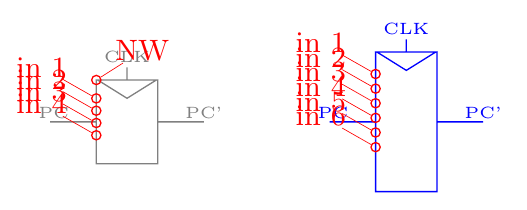
\begin{tikzpicture}
\node [draw,reg,minimum width=3cm, minimum height=3cm, black!50] (PC1) at (0,0) {};
\path (PC1.north west) \showcoord(NW)<45:0.2>;
\node [draw, reg,black!50,minimum width=3cm, minimum height=5cm, ports=6, blue] (PC2) at (3,0) {};
\foreach \p in {1,...,4} \path(PC1.in \p) \showcoord(in \p)<145:0.3>;
\foreach \p in {1,...,6} \path(PC2.in \p) \showcoord(in \p)<145:0.3>;
\end{tikzpicture}
\end{document}https://stackoverflow.com/questions/61729168
复制相似问题
腾讯云开发者

Copyright © 2013 - 2026 Tencent Cloud. All Rights Reserved. 腾讯云 版权所有
深圳市腾讯计算机系统有限公司 ICP备案/许可证号:粤B2-20090059 ![]() 粤公网安备44030502008569号
粤公网安备44030502008569号
腾讯云计算(北京)有限责任公司 京ICP证150476号 | 京ICP备11018762号