
内置led不会打开STM32F303RE核心板
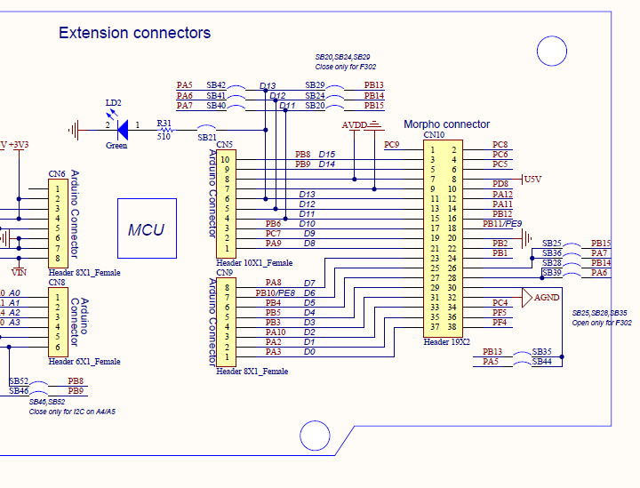
我试图把led (在原理图中的LD2)转到核子板内,只使用STM32CubeIDE寄存器。
用户手册列出时钟、模式和数据寄存器的下列地址:
Led pin: PA5
Address of the Clock control register: RCC_AHBENR
[base address] + [offset] ===> [Result]
0x4002 1000 + 0x14 ===> 0x40021014
Address of the GPIOA mode register
0x4800 0000 + 0x00 ===> 0x48000000
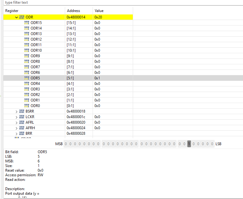
Address of the GPIOA output data register
0x4800 0000 + 0x14 ===> 0x48000014我使用以下代码来设置/清除董事会中的寄存器:
#include <stdint.h>

int main(void)
{
    uint32_t *pClkCtrlReg = (uint32_t*)0x40021014;
    uint32_t *pPortAModeReg = (uint32_t*)0x48000000;
    uint32_t *pPortAOutReg = (uint32_t*)0x48000014;

    //1. enable the clock for GPIOA peripheral in the AHBENR
    *pClkCtrlReg |= 0x00020000;

    //2. configure the mode of the IO pin as output
    //a. clear the 24th and 25th bit positions
    *pPortAModeReg &= 0xFCFFFFFF;
    //b set 24th bit position as 1
    *pPortAModeReg |= 0x01000000;

    //3. SET 12th bit of the output data register to make I/O pin-12 as HIGH
    *pPortAOutReg |= 0x20;


    while(1);
}
使用IDE中的寄存器查看器,我可以看到PA5被设置为输出,但实际上,我的led没有打开。
我不知道我做错了什么。我怀疑引脚PA5是错的,但我也尝试了PA12,但它不起作用。有人能帮帮我吗?
回答 3
Stack Overflow用户
发布于 2022-07-07 08:48:51
我手拿着参考手册浏览了你的代码。RM0316 STM32F303参考手册。
您正确地激活了GPIO端口A的时钟(而且,GPIOA寄存器也会读取所有的0x00,因为它没有被激活)。
然后将GPIO模式设置为,引用如下:
//2. configure the mode of the IO pin as output
//a. clear the 24th and 25th bit positions
*pPortAModeReg &= 0xFCFFFFFF;
//b set 24th bit position as 1
*pPortAModeReg |= 0x01000000;
你和第24和25位一起工作。这些都是:
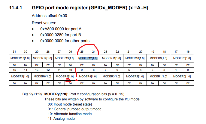
所以您为pin A12而不是A5设置了模式。对于GPIOA 5,您需要操作位10和11。
//clear pin5 bits
*pPortAModeReg &= ~(0x03 << 10); //take 0b11, shift it to position 10, flip all bits, AND with original state of register
然后将这些位设置为“通用输出模式”01,这也是对错误位所做的:
//b set 10th bit position as 1
*pPortAModeReg |= (0x01 << 10);
我检查了所有的寄存器,GPIO有,不应该有任何其他您需要设置。如果事情仍然不工作,请张贴所有GPIOA寄存器的内容。
编辑:同样,尝试使用位设置/重置寄存器。注意,它们是只读的,所以它们没有"|=“,只有"=”。给他们写0不起什么作用。因此,您只需将(0x01<<5)直接写入GPIOA寄存器。
GPIOA->BSRR = (1U<<5); //or however you want to address that registerStack Overflow用户
发布于 2022-07-07 14:21:22
关于您的代码的几点评论:
- 养成在访问外围寄存器时始终使用
volatile关键字的习惯。否则编译器可能会优化您的代码。为了不忘记,我通常为类似于reg32_t类型的东西创建typedef。 - 正如OP所指出的,使用表单
(1 << b)的代码可以清楚地显示您所引用的是哪个位。您的编译器将对此进行优化,因此编译后的代码的最终结果将是相同的。您甚至可以考虑将其转换为几个宏或内联函数。 - 当您对外围寄存器进行几次更改时,最好将其复制;对副本进行更改;然后将副本存储回寄存器。这样,您就不会暂时将寄存器置于不需要的状态。
下面是您进行这些更改的代码:
#include <stdint.h>

typedef volatile uint32_t reg32_t;

int main(void)
{
    reg32_t *pClkCtrlReg = (reg32_t*)0x40021014;
    reg32_t *pPortAModeReg = (reg32_t*)0x48000000;
    reg32_t *pPortABsrReg = (reg32_t*)0x48000018;

    //1. enable the clock for GPIOA peripheral in the AHBENR
    *pClkCtrlReg |= (1<<17);

    //2. configure the mode of the IO pin as output
    uint32_t modereg = *pPortAModeReg & ~(3<<(2*5));
    modereg |= (1<<(2*5));
    *pPortAModeReg = modereg;

    //3. SET 5th bit of the bit set/reset register to make I/O pin 5 HIGH
    *pPortABsrReg = (1<<5);

    // If you want to turn the LED back off at a later time, do this:
    // *pPortABsrReg = (1<<(5+16));

    for (;;) ;
}
祝你的眼花缭乱!
Stack Overflow用户
发布于 2022-07-07 06:39:54
//3.设置输出数据寄存器的12位以使I/O pin-12高
*pPortAOutReg |= 0x20;对于PIN 12,值应该是*pPortAOutReg |= 0x1000;
或者您可以这样做:使用这个*pPortAOutReg |= (1 << 12);,您不需要知道非常高的值。
https://stackoverflow.com/questions/72892782
复制相似问题
腾讯云开发者

Copyright © 2013 - 2026 Tencent Cloud. All Rights Reserved. 腾讯云 版权所有
深圳市腾讯计算机系统有限公司 ICP备案/许可证号:粤B2-20090059 ![]() 粤公网安备44030502008569号
粤公网安备44030502008569号
腾讯云计算(北京)有限责任公司 京ICP证150476号 | 京ICP备11018762号