
二维图像算法中陀螺图案的生成
我试图在一定的间距下用一定厚度的陀螺仪线填充图像,但数学不是我的领域。我能够创造一个正弦波,并在X方向移动一点,使它看起来像一个陀螺仪,但它是不一样的。
其背后的想法是将一些分辨率相同的图像叠加起来,并将陀螺仪复制成2D图像,所以我们还有XYZ,其中Z可以是每层0.01mm到0.1mm。
我试过的是:
int sineHeight = 100;
int sineWidth = 100;
int spacing = 100;
int radius = 10;

for (int y1 = 0; y1 < mat.Height; y1 += sineHeight+spacing)
for (int x = 0; x < mat.Width; x++)
{
    // Simulating first image
    int y2 = (int)(Math.Sin((double)x / sineWidth) * sineHeight / 2.0 + sineHeight / 2.0 + radius);
    Circle(mat, new System.Drawing.Point(x, y1+y2), radius, EmguExtensions.WhiteColor, -1, LineType.AntiAlias);

    // Simulating second image, shift by x to make it look a bit more with gyroid
    y2 = (int)(Math.Sin((double)x / sineWidth + sineWidth) * sineHeight / 2.0 + sineHeight / 2.0 + radius);
    Circle(mat, new System.Drawing.Point(x, y1 + y2), radius, EmguExtensions.GreyColor, -1, LineType.AntiAlias);
}
结果:(白色代表第一层,灰色表示第二层)
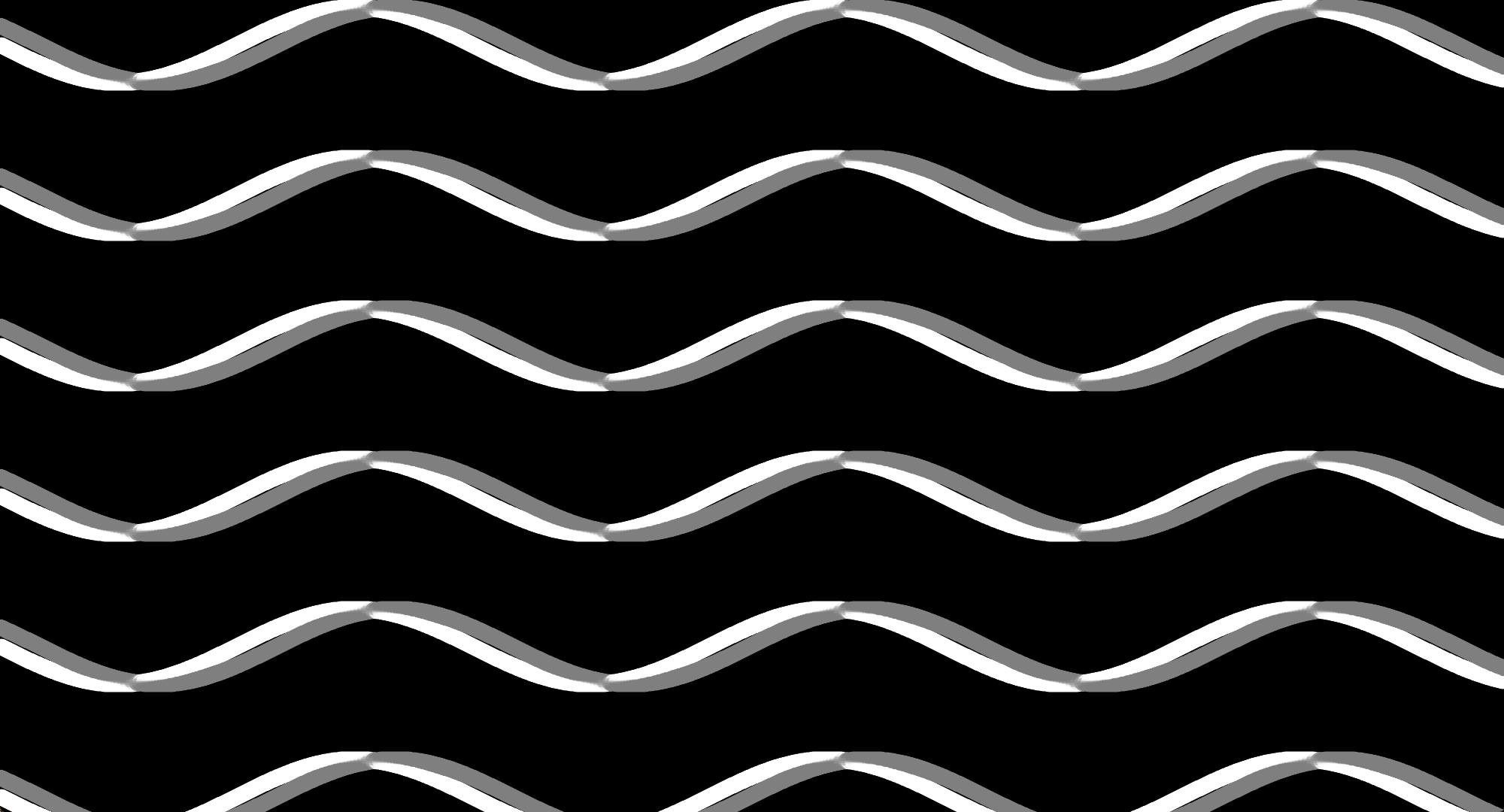
尽管如此,这看起来并不像真正的陀螺仪,我如何复制公式在这个空间中工作呢?
回答 1
Stack Overflow用户
发布于 2022-03-27 10:13:59
您只有一个丑陋的片段,因为我在您的代码中没有看到任何z (它是正确的,表面有水平和垂直的正弦波,像这样,z中的每个0.5*pi都是这样的)。
要想看到三维表面,你必须用射线照射z .
我希望对一些小的非零数(如x,y,z )的陀螺方程的实际迭代结果进行有条件的检验,然后才画出内容,或者从结果中计算颜色。这是在GLSL中理想的做法。
如果您不熟悉GLSL和着色器,则对呈现的四角体的每个像素(称为片段)执行片段着色器,因此您只需将代码放入嵌套的x,y for循环中,并使用您的x,y而不是pos (您可以忽略顶点着色器并不重要)。
您有两个基本选项来呈现这个选项:
混合光线铸造的表面像素与一起创建X射线类图像.它可以与SSS技术相结合,获得玻璃或半透明材料的印模。下面是用于混合的简单GLSL示例:
顶点:
#version 400 core

in vec2 position;
out vec2 pos;

void main(void)
    {
    pos=position;
    gl_Position = vec4(position.xy,0.0,1.0);
    }
片段:
#version 400 core
in vec2 pos;
out vec3 out_col;
void main(void)
{
float n,x,y,z,dz,d,i,di;
const float scale=2.0*3.1415926535897932384626433832795;
n=100.0; // layers
x=pos.x*scale; // x postion of pixel
y=pos.y*scale; // y postion of pixel
dz=2.0*scale/n; // z step
di=1.0/n; // color increment
i=0.0; // color intensity
for (z=-scale;z<=scale;z+=dz) // do all layers
{
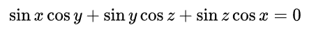
d =sin(x)*cos(y); // compute gyroid equation
d+=sin(y)*cos(z);
d+=sin(z)*cos(x);
if (d<=1e-6) i+=di; // if near surface add to color
}
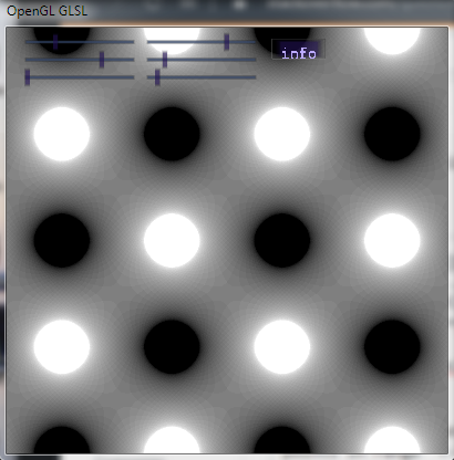
out_col=vec3(1.0,1.0,1.0)*i;
}使用简单,只需渲染2D四面屏,没有任何矩阵与角pos点在范围内的<-1,+1>。结果如下:
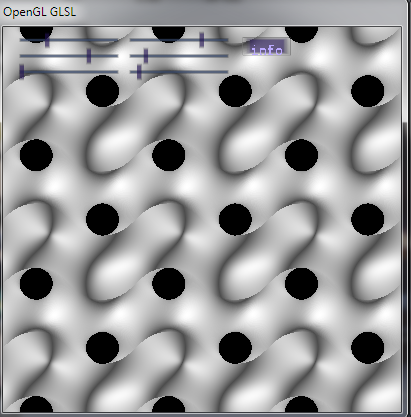
另一种技术是渲染第一次击中表面,创建网格类图像。为了看细节,我们需要添加基本(双面)方向照明,其中表面正常是需要的。利用x,y,z对方程进行简单的部分推导,可以计算出法态。因为现在的表面是不透明的,那么我们可以停止在第一次击中和光线投射,只是在z的单一时期,因为任何事情之后,都是隐藏的。这里是一个简单的例子:
片段:
#version 400 core

in vec2 pos;                        // input fragmen (pixel) position <-1,+1>
out vec3 col;                       // output fragment (pixel) RGB color <0,1>

void main(void)
    {
    bool _discard=true;
    float N,x,y,z,dz,d,i;
    vec3 n,l;
    const float pi=3.1415926535897932384626433832795;
    const float scale =3.0*pi;      // 3.0 periods in x,y
    const float scalez=2.0*pi;      // 1.0 period in z
    N=200.0;                        // layers per z (quality)
    x=pos.x*scale;                  // <-1,+1> -> [rad]
    y=pos.y*scale;                  // <-1,+1> -> [rad]
    dz=2.0*scalez/N;                // z step
    l=vec3(0.0,0.0,1.0);            // light unit direction
    i=0.0;                          // starting color intensity
    n=vec3(0.0,0.0,1.0);            // starting normal only to get rid o warning
    for (z=0.0;z>=-scalez;z-=dz)    // raycast z through all layers in view direction
        {
        // gyroid equation
        d =sin(x)*cos(y);           // compute gyroid equation
        d+=sin(y)*cos(z);
        d+=sin(z)*cos(x);
        // surface hit test
        if (d>1e-6) continue;       // skip if too far from surface
        _discard=false;             // remember that surface was hit
        // compute normal
        n.x =+cos(x)*cos(y);        // partial derivate by x
        n.x+=+sin(y)*cos(z);
        n.x+=-sin(z)*sin(x);
        n.y =-sin(x)*sin(y);        // partial derivate by y
        n.y+=+cos(y)*cos(z);
        n.y+=+sin(z)*cos(x);
        n.z =+sin(x)*cos(y);        // partial derivate by z
        n.z+=-sin(y)*sin(z);
        n.z+=+cos(z)*cos(x);
        break;                      // stop raycasting
        }
    // skip rendering if no hit with surface (hole)
    if (_discard) discard;
    // directional lighting
    n=normalize(n);
    i=abs(dot(l,n));
    // ambient + directional lighting
    i=0.3+(0.7*i);
    // output fragment (render pixel)
    gl_FragDepth=z;                 // depth (optional)
    col=vec3(1.0,1.0,1.0)*i;        // color
    }
我希望我没有在部分派生词中犯错误。结果如下:
Edit1
基于您的代码,我看到它是这样的(X射线像混合)
var mat = EmguExtensions.InitMat(new System.Drawing.Size(2000, 1080));
double zz, dz, d, i, di = 0;
const double scalex = 2.0 * Math.PI / mat.Width;
const double scaley = 2.0 * Math.PI / mat.Height;
const double scalez = 2.0 * Math.PI;
uint layerCount = 100;            // layers
for (int y = 0; y < mat.Height; y++)
    {
        double yy = y * scaley; // y position of pixel
        for (int x = 0; x < mat.Width; x++)
            {
            double xx = x * scalex; // x position of pixel
            dz = 2.0 * scalez / layerCount; // z step
            di = 1.0 / layerCount; // color increment
            i = 0.0; // color intensity
            for (zz = -scalez; zz <= scalez; zz += dz) // do all layers
        {
        d =  Math.Sin(xx) * Math.Cos(yy); // compute gyroid equation
        d += Math.Sin(yy) * Math.Cos(zz);
        d += Math.Sin(zz) * Math.Cos(xx);
        if (d > 1e-6) continue;
        i += di; // if near surface add to color
        }
    i*=255.0;
    mat.SetByte(x, y, (byte)(i));
    }
}https://stackoverflow.com/questions/71632260
复制相似问题
腾讯云开发者

Copyright © 2013 - 2026 Tencent Cloud. All Rights Reserved. 腾讯云 版权所有
深圳市腾讯计算机系统有限公司 ICP备案/许可证号:粤B2-20090059 ![]() 粤公网安备44030502008569号
粤公网安备44030502008569号
腾讯云计算(北京)有限责任公司 京ICP证150476号 | 京ICP备11018762号