
从鼠标位置计算和绘制网格表面的三维点
我需要在网格表面绘制一组3D点(可以是曲线/字体),以便以后可以检索到它们,因此纹理上的渲染点和附加纹理不起作用。这些点将通过鼠标点击绘制/编辑。这是为了CAD的目的,所以精度是很重要的。
- 如何从二维鼠标位置得到网格局部坐标下的三维顶点?
我使用OpenGL作为呈现部分,并使用以下
glm::perspective()创建透视图投影: 宽径比= 16 :9 zNear = 0.1f zFar = 100.0f三角网格 - 是否可以在物体空间中进行光线-三角形相交的计算?
- 相机的位置(起源)必须是世界空间吗?
回答 1
Stack Overflow用户
发布于 2022-03-07 13:54:51
您需要的是(假设旧的api OpenGL默认标记):
- 透视投影:
FOVx,FOVy,znear Model*View矩阵的逆- 鼠标位置转换为
<-1,+1>范围 - 由网格组成的三角形列表
你可以这样做:
- 从相机原点投射射线
- 将其转换为网格局部坐标
- 计算最近的射线/三角形交点
是的,您可以在网格局部坐标中计算这个值,在这种情况下,您需要在相同的坐标下使用Ray。
这里简单的C++/旧api OpenGL/VCL示例:
//---------------------------------------------------------------------------
#include <vcl.h>
#include <math.h>
#include "gl_simple.h"
#include "GLSL_math.h"
#pragma hdrstop
#include "Unit1.h"
//---------------------------------------------------------------------------
#pragma package(smart_init)
#pragma resource "*.dfm"
TForm1 *Form1;
//---------------------------------------------------------------------------
float mx=0.0,my=0.0;    // mouse position
//---------------------------------------------------------------------------
// Icosahedron
#define icoX .525731112119133606
#define icoZ .850650808352039932
const GLfloat vdata[12][3] =
    {
    {-icoX,0.0,icoZ}, {icoX,0.0,icoZ}, {-icoX,0.0,-icoZ}, {icoX,0.0,-icoZ},
    {0.0,icoZ,icoX}, {0.0,icoZ,-icoX}, {0.0,-icoZ,icoX}, {0.0,-icoZ,-icoX},
    {icoZ,icoX,0.0}, {-icoZ,icoX,0.0}, {icoZ,-icoX,0.0}, {-icoZ,-icoX,0.0},
    };
const int tindices=20;
const GLuint tindice[tindices][3] =
    {
    {0,4,1}, {0,9,4}, {9,5,4}, {4,5,8}, {4,8,1},
    {8,10,1}, {8,3,10}, {5,3,8}, {5,2,3}, {2,7,3},
    {7,10,3}, {7,6,10}, {7,11,6}, {11,0,6}, {0,1,6},
    {6,1,10}, {9,0,11}, {9,11,2}, {9,2,5}, {7,2,11}
    };
//---------------------------------------------------------------------------
void icosahedron_draw() // renders mesh using old api
    {
    int i;
    GLfloat nx,ny,nz;
    glEnable(GL_CULL_FACE);
    glFrontFace(GL_CW);
    glBegin(GL_TRIANGLES);
    for (i=0;i<tindices;i++)
        {
        nx =vdata[tindice[i][0]][0];
        ny =vdata[tindice[i][0]][1];
        nz =vdata[tindice[i][0]][2];
        nx+=vdata[tindice[i][1]][0];
        ny+=vdata[tindice[i][1]][1];
        nz+=vdata[tindice[i][1]][2];
        nx+=vdata[tindice[i][2]][0]; nx/=3.0;
        ny+=vdata[tindice[i][2]][1]; ny/=3.0;
        nz+=vdata[tindice[i][2]][2]; nz/=3.0;
        glNormal3f(nx,ny,nz);
        glVertex3fv(vdata[tindice[i][0]]);
        glVertex3fv(vdata[tindice[i][1]]);
        glVertex3fv(vdata[tindice[i][2]]);
        }
    glEnd();
    }
//---------------------------------------------------------------------------
vec3 ray_pick(float mx,float my,mat4 _mv)   // return closest intersection using mouse mx,my <-1,+1> position and inverse of ModelView _mv
    {
    // Perspective settings
    const float deg=M_PI/180.0;
    const float _zero=1e-6;
    float znear=0.1;
    float FOVy=45.0*deg;
    float FOVx=FOVy*xs/ys;  // use aspect ratio if you do not know screen resolution
    // Ray endpoints in camera local coordinates
    vec3 pos=vec3(mx*tan(0.5*FOVx)*znear,my*tan(0.5*FOVy)*znear,-znear);
    vec3 dir=vec3(0.0,0.0,0.0);
    // Transform to mesh local coordinates
    pos=(_mv*vec4(pos,1.0)).xyz;
    dir=(_mv*vec4(dir,1.0)).xyz;
    // convert endpoint to direction
    dir=normalize(pos-dir);
    // needed variables
    vec3 pnt=vec3(0.0,0.0,0.0);
    vec3 v0,v1,v2,e1,e2,n,p,q,r;
    int i,ii=1;
    float t=-1.0,tt=-1.0,u,v,det,idet;
    // loop through all triangles
    for (int i=0;i<tindices;i++)
        {
        // load v0,v1,v2 with actual triangle
        v0.x=vdata[tindice[i][0]][0];
        v0.y=vdata[tindice[i][0]][1];
        v0.z=vdata[tindice[i][0]][2];
        v1.x=vdata[tindice[i][1]][0];
        v1.y=vdata[tindice[i][1]][1];
        v1.z=vdata[tindice[i][1]][2];
        v2.x=vdata[tindice[i][2]][0];
        v2.y=vdata[tindice[i][2]][1];
        v2.z=vdata[tindice[i][2]][2];
        //compute ray(pos,dir) triangle(v0,v1,v2) intersection
        e1=v1-v0;
        e2=v2-v0;
        // Calculate planes normal vector
        p=cross(dir,e2);
        det=dot(e1,p);
        // Ray is parallel to plane
        if (abs(det)<1e-8) continue;
        idet=1.0/det;
        r=pos-v0;
        u=dot(r,p)*idet;
        if ((u<0.0)||(u>1.0)) continue;
        q=cross(r,e1);
        v=dot(dir,q)*idet;
        if ((v<0.0)||(u+v>1.0)) continue;
        t=dot(e2,q)*idet;
        // remember closest intersection to camera
        if ((t>_zero)&&((t<=tt)||(ii!=0)))
            {
            ii=0; tt=t;
            // barycentric interpolate position
            t=1.0-u-v;
            pnt=(v0*t)+(v1*u)+(v2*v);
            }
        }
    return pnt; // if (ii==1) no intersection found
    }
//---------------------------------------------------------------------------
void gl_draw()
    {
    glClear(GL_COLOR_BUFFER_BIT|GL_DEPTH_BUFFER_BIT);
    glDisable(GL_TEXTURE_2D);
    glEnable(GL_DEPTH_TEST);
    glEnable(GL_LIGHT0);
    glEnable(GL_CULL_FACE);
//  glDisable(GL_CULL_FACE);
    glFrontFace(GL_CCW);
    glEnable(GL_COLOR_MATERIAL);
/*
    glPolygonMode(GL_FRONT,GL_FILL);
    glPolygonMode(GL_BACK,GL_LINE);
    glDisable(GL_CULL_FACE);
*/
    // set projection
    glMatrixMode(GL_PROJECTION);        // operacie s projekcnou maticou
    glLoadIdentity();                   // jednotkova matica projekcie
    gluPerspective(45,float(xs)/float(ys),0.1,100.0); // matica=perspektiva,120 stupnov premieta z viewsize do 0.1

    // set view
    glMatrixMode(GL_MODELVIEW);
    glLoadIdentity();
    glTranslatef(0.2,0.0,-5.0);
    static float ang=0.0;
    glRotatef(ang,0.2,0.7,0.2); ang+=5.0; if (ang>=360.0) ang-=360.0;

    // obtain actual modelview matrix (mv) and its inverse (_mv)
    mat4 mv,_mv;
    float m[16];
    glGetFloatv(GL_MODELVIEW_MATRIX,m);
    mv.set(m);
    _mv=inverse(mv);

    // render mesh
    glColor3f(0.5,0.5,0.5);
    glEnable(GL_LIGHTING);
    icosahedron_draw();
    glDisable(GL_LIGHTING);

    // get point mouse points to
    vec3 p=ray_pick(mx,my,_mv);

    // render it for visual check
    float r=0.1;
    glColor3f(1.0,1.0,0.0);
    glBegin(GL_LINES);
    glVertex3f(p.x-r,p.y,p.z); glVertex3f(p.x+r,p.y,p.z);
    glVertex3f(p.x,p.y-r,p.z); glVertex3f(p.x,p.y+r,p.z);
    glVertex3f(p.x,p.y,p.z-r); glVertex3f(p.x,p.y,p.z+r);
    glEnd();

//  glFlush();
    glFinish();
    SwapBuffers(hdc);
    }
//---------------------------------------------------------------------------
__fastcall TForm1::TForm1(TComponent* Owner):TForm(Owner)
    {
    // Init of program
    gl_init(Handle);    // init OpenGL
    }
//---------------------------------------------------------------------------
void __fastcall TForm1::FormDestroy(TObject *Sender)
    {
    // Exit of program
    gl_exit();
    }
//---------------------------------------------------------------------------
void __fastcall TForm1::FormPaint(TObject *Sender)
    {
    // repaint
    gl_draw();
    }
//---------------------------------------------------------------------------
void __fastcall TForm1::FormResize(TObject *Sender)
    {
    // resize
    gl_resize(ClientWidth,ClientHeight);
    }
//---------------------------------------------------------------------------
void __fastcall TForm1::tim_redrawTimer(TObject *Sender)
    {
    gl_draw();
    }
//---------------------------------------------------------------------------
void __fastcall TForm1::FormMouseMove(TObject *Sender, TShiftState Shift, int X, int Y)
    {
    // just event to obtain actual mouse position
    // and convert it from screen coordinates <0,xs),<0,ys) to <-1,+1> range
    mx=X; mx=(2.0*mx/float(xs-1))-1.0;
    my=Y; my=1.0-(2.0*my/float(ys-1)); // y is mirrored in OpenGL
    }
//---------------------------------------------------------------------------唯一重要的是函数ray_pick,它根据鼠标的二维位置和ModelView矩阵的实际逆返回你的三维点。
在这里预览:
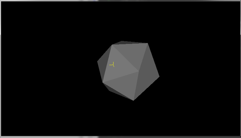
我渲染黄色十字在发现的三维位置,因为你可以看到它与表面直接接触(因为它的一半线在表面之下)。
在通常情况下,我使用了我的库:simple.h用于创建OpenGL上下文,math.h用于向量和矩阵数学,而不是GLM。但是无论如何都可以创建GL上下文,您也可以使用您所拥有的进行数学计算(我认为语法也与GLM相同,因为它们也试图模仿GLSL .)
对于方面1:1,这个方法工作得很好,在矩形方面,它在离屏幕中心越远的地方稍微不精确(很可能是因为我使用了raw gluPerspective,其中包含一些不精确的术语,或者我在创建光线时忽略了一些校正,但我对此表示怀疑)。
如果您不需要高精度(而不是CAD/CAM需要尽可能高的精度),您可以摆脱光线网格交点,直接在鼠标位置选择深度缓冲区,并从中计算出结果点(不需要网格)。
有关的更多信息,请参见相关的QAs:
https://stackoverflow.com/questions/71377048
复制相似问题
腾讯云开发者

Copyright © 2013 - 2026 Tencent Cloud. All Rights Reserved. 腾讯云 版权所有
深圳市腾讯计算机系统有限公司 ICP备案/许可证号:粤B2-20090059 ![]() 粤公网安备44030502008569号
粤公网安备44030502008569号
腾讯云计算(北京)有限责任公司 京ICP证150476号 | 京ICP备11018762号